--
five vertical divisions. The arbitrary deflection factor
is
then
determined
by
substituting values
in
the formula:
Arbitrary
Deflection = 1.5 x 1 V
/div
= 1.5 V
/div
Factor
The amplitude
of
the unknown signal can then
be
deter-
mined
by
substituting values
in
the unknown signal ampli-
tude formula:
Amplitude = 1.5 V
/div
X 5 div = 7.5 V
FREQUENCY
The frequency
of
a recurrent signal can
be
determined
from its time-duration measurement as follows:
1.
Measure the time duration
of
one waveform cycle
using the preceding "Time Duration" measurement pro-
cedure.
2.
Calculate the reciprocal of the time-duration value to
determine the frequency
of
the waveform.
EXAMPLE: The signal
in
Figure
6-21
has a time dura-
tion
of
16.6
ms.
Calculating the reciprocal
of
time duration:
Frequency =
-----
time duration
RISE
TIME
--
1
--
=
60
Hz
16.6 ms
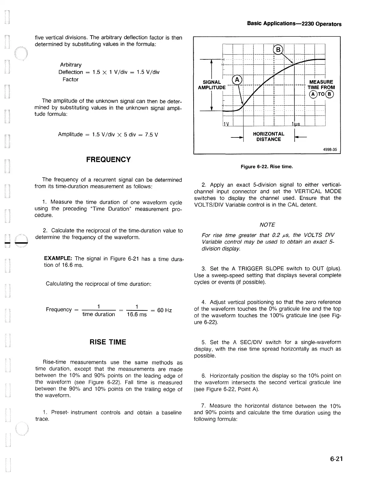
Rise-time measurements
use
the same methods
as
time duration, except that the measurements are made
between the 1
0%
and 90% points on the leading edge
of
the waveform (see Figure 6-22).
Fall
time
is
measured
between the 90%
and
10% points
on
the trailing edge of
the waveform.
1.
Preset, instrument controls and obtain a baseline
trace.
I
I
T
100
•
I
90
r
I
SIGNAL
AMPLITUD
E.
J_
I
,r
I
i
l1v
Basic Applications-2230 Operators
,..BJ
..
I"-.:
.-
/
V
A)
V
\
V
\/
~
-·
1 I<>
HORIZONTAL
MEASU
RE
ROM
TIMEF
@To
®
-
DISTANCE
~
4998-35
Figure 6-22. Rise time.
2.
Apply
an
exact 5-division signal to either vertical-
channel input connector and set the VERTICAL MODE
switches to display the channel used. Ensure that the
VOL TS/DIV Variable control is
in
the CAL detent.
NOTE
For rise time greater that 0.2
µS,
the
VOL
TS
DIV
Variable control may be used to obtain an exact 5-
division display.
3.
Set the A TRIGGER SLOPE switch to OUT (plus).
Use a sweep-speed setting that displays several complete
cycles or events (if possible).
4.
Adjust vertical positioning so that the zero reference
of
the waveform touches the 0% graticule line and the top
of
the waveform touches the 100% graticule line (see Fig-
ure 6-22).
5.
Set the A SEC/DIV switch for a single-waveform
display, with the rise time spread horizontally
as
much
as
possible.
6.
Horizontally position the display so the 1 0% point
on
the waveform intersects the second vertical graticule line
(see Figure 6-22, Point
A).
7.
Measure the horizontal distance between the 10%
and 90% points and calculate the time duration using the
following formula:
6-21

 Loading...


