Basic
Applications-2230
Operators
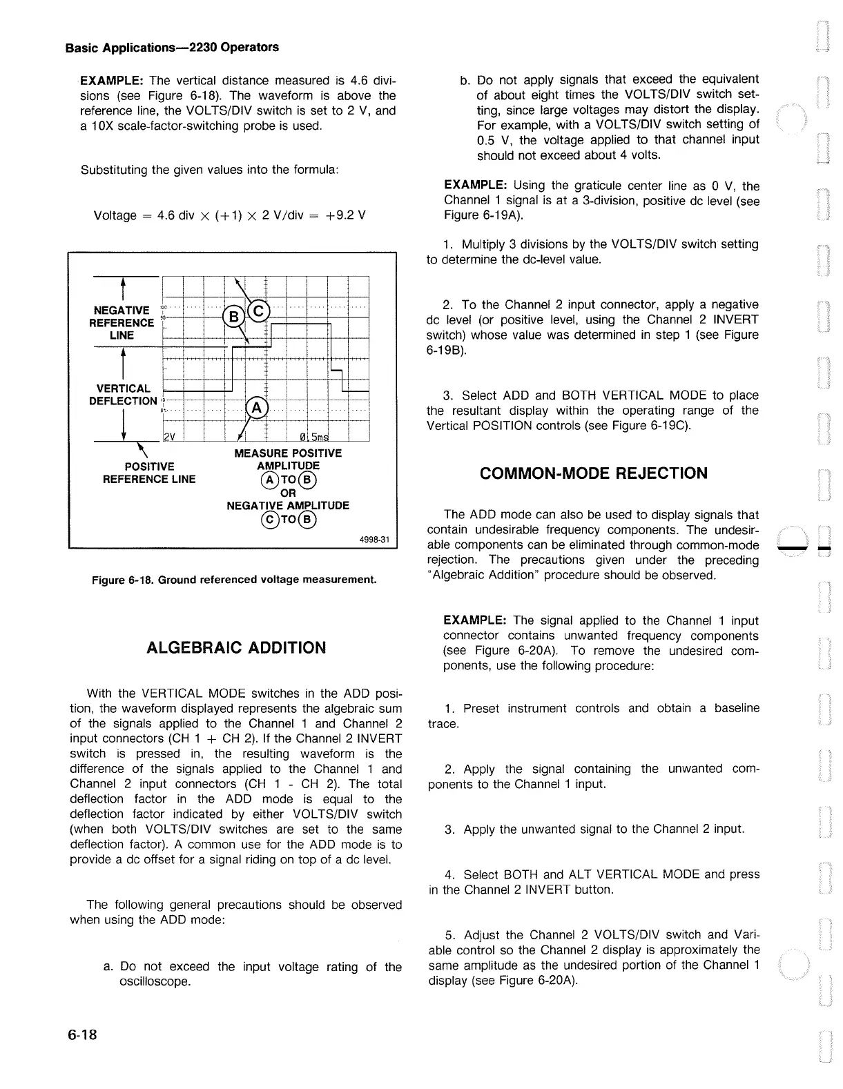
EXAMPLE: The vertical distance measured is 4.6 divi-
sions (see Figure 6-18). The waveform
is
above the
reference line, the VOL TS/DIV switch
is
set to 2
V,
and
a 1
OX
scale-factor-switching probe
is
used.
Substituting the given values into the formula:
Voltage=
4.6 div X
(+1)
X 2 V/div =
+9.2
V
t
NEGATIVE
'1°
REFERENCE y--1--__,___.
LINE
t
VERTICAL
DEFLECTION
'1-+---+--+-
---¾-
•:.~V~·
-~-~M-~E-AS~U_R_E~P~OSITIVE
POSITIVE
REFERENCE LINE
AMPLITUDE
@rn®
OR
NEGATIVE AMPLITUDE
@rn®
4998-31
Figure 6-18. Ground referenced voltage measurement.
ALGEBRAIC ADDITION
With the VERTICAL MODE switches
in
the ADD posi-
tion, the waveform displayed represents the algebraic sum
of
the signals applied to the Channel 1
and
Channel 2
input connectors
(CH
1 +
CH
2).
If the Channel 2 INVERT
switch
is
pressed
in,
the resulting waveform is the
difference
of
the signals applied to the Channel 1
and
Channel 2 input connectors
(CH
1 -
CH
2).
The total
deflection factor
in
the ADD mode
is
equal to the
deflection factor indicated by either VOL TS/DIV switch
(when both VOL TS/DIV switches
are
set to the same
deflection factor). A common use for the ADD mode
is
to
provide a
de
offset for a signal riding
on
top of a
de
level.
The following general precautions should
be
observed
when using the ADD mode:
6-18
a.
Do not exceed the input voltage rating of the
oscilloscope.
b.
Do not apply signals that exceed the equivalent
of
about eight times the VOL TS/DIV switch set-
ting, since large voltages may distort the display.
For example, with a VOL TS/DIV switch setting
of
0.5
V,
the voltage applied to that channel input
should not exceed about 4 volts.
EXAMPLE: Using the graticule center line
as
O
V,
the
Channel 1 signal is at a 3-division, positive
de
level (see
Figure 6-19A).
1.
Multiply 3 divisions by the VOL TS/DIV switch setting
to determine the de-level value.
2.
To the Channel 2 input connector, apply a negative
de
level (or positive level, using the Channel 2 INVERT
switch) whose value was determined
in
step 1
(see
Figure
6-19B).
3.
Select ADD and BOTH VERTICAL MODE
to
place
the resultant display within the operating range of the
Vertical POSITION controls
(see
Figure 6-19C).
COMMON-MODE REJECTION
The ADD mode can also
be
used to display signals that
contain undesirable frequency components. The undesir-
able components can
be
eliminated through common-mode
rejection. The precautions given under the preceding
"Algebraic Addition" procedure should
be
observed.
EXAMPLE: The signal applied to the Channel 1 input
connector contains unwanted frequency components
(see
Figure 6-20A). To remove the undesired com-
ponents, use the following procedure:
1.
Preset instrument controls
and
obtain a baseline
trace.
2.
Apply the signal containing the unwanted com-
ponents to the Channel 1 input.
3.
Apply the unwanted signal to the Channel 2 input.
4.
Select BOTH
and
ALT VERTICAL MODE and press
in
the Channel 2 INVERT button.
5.
Adjust the Channel 2 VOL TS/DIV switch
and
Vari-
able control
so
the Channel 2 display
is
approximately the
same amplitude
as
the undesired portion of the Channel 1
display (see Figure 6-20A).
--

 Loading...


