Basic Applications-2230 Operators
Time Difference Between Two Time-Related
Pulses
1.
Set the VERTICAL MODE switches to BOTH and
ALT.
2.
Use probes or coaxial cables with equal time delay
to
apply the pulse signals
to
be
measured to the input
connectors; one to Channel 1 and the second to Chan-
nel
2.
3.
Set the VOL TS/DIV switches to obtain about three
divisions
of
display amplitude for each signal.
4.
Set the STORE/NON STORE switch to STORE
(button
in),
set the A TRIGGER Mode switch to NORM,
set the A SOURCE switch
to
INT, and set the A&B INT
switch to
CH
1.
5.
Adjust the A TRIGGER LEVEL and SLOPE control
for a continuous, triggered acquisition of the signals.
6.
Set the A SEC/DIV switch to obtain a display of the
measurement points on the
two
pulses between which the
measurement
is
to
be
made.
7.
Set the PRETRIG/POST TRIG switch
as
required to
obtain the entire pulse display.
8.
Press the SAVE/CONTINUE switch to the SAVE
position (button
in)
to save the waveform and to present a
more stable display for measurement. Cursors will appear
on both the Channel 1 and Channel 2 traces
in
SAVE
mode.
9.
Set the POSITION CURS/SELECT WAVEFORM
switch to the POSITION CURS position (button
in).
10. Use the CURSORS control to move the active cur-
sor
to the 50% point
of
the Channel 1 pulse leading edge.
NOTE
Pulses with a fast rise time have only a few sample
points on
the
leading edge, and
it
may
not
be possi-
ble to place the
dot
at
exactly the 50% level on the
leading edge.
6-10
ltiV1=
5.8
~v
T
ti
=0.
4911s
tiV2,
F2.2
~v
t
T
I
-
-
~
~
r n
00 ·
....
I
0
I
I
~~
CHANNE
..t:.:'3.-
-
-
J
L
L 1
CURS ORS
r
l'---Js:ca
'~~\
.
--
CHANNE
L2
Is/
2V
0
lm~
4998-21
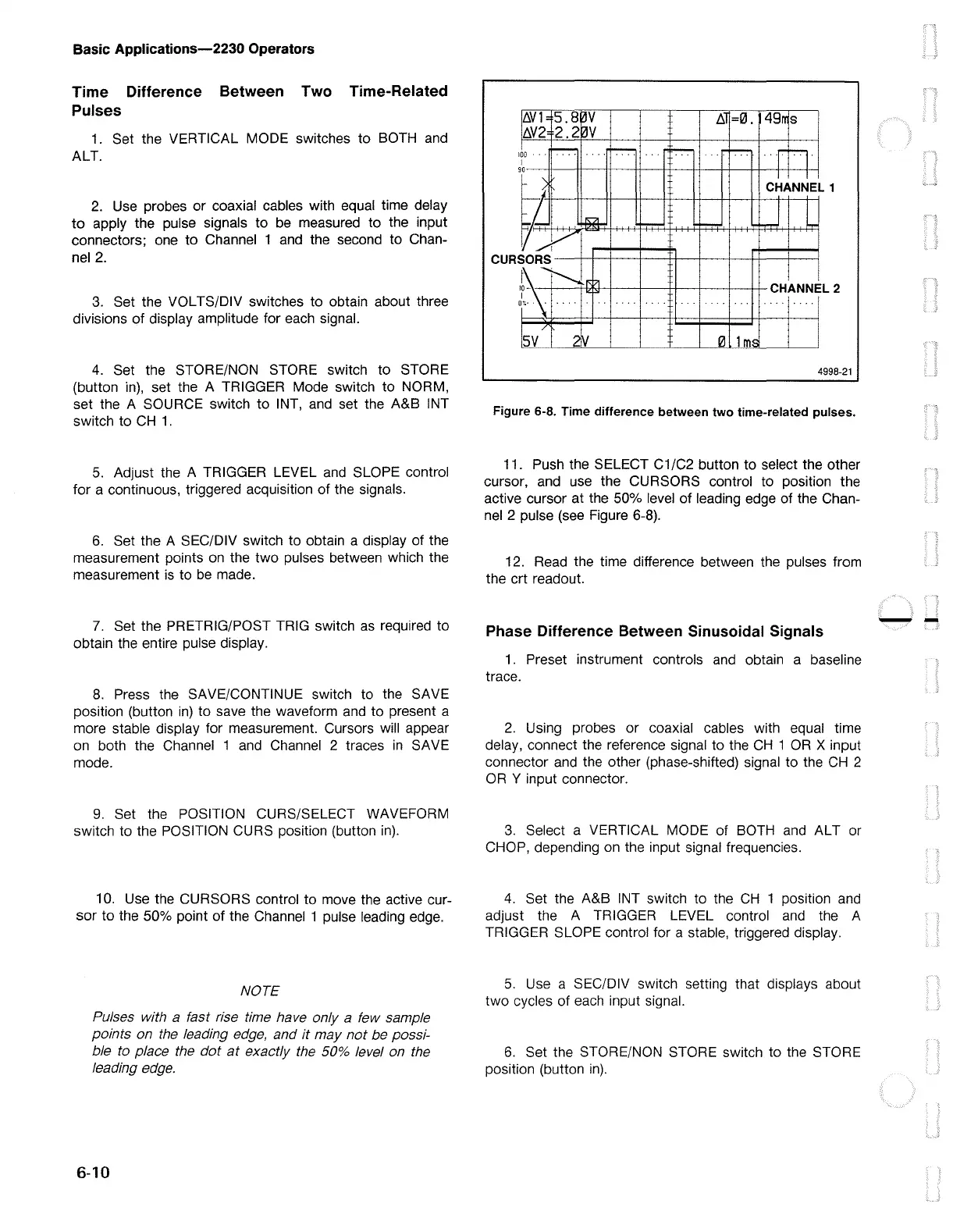
Figure 6-8. Time difference between two time-related pulses.
11. Push the SELECT C1/C2 button to select the other
cursor, and use the CURSORS control to position the
active cursor at the 50% level
of
leading edge
of
the Chan-
nel 2 pulse (see Figure 6-8).
12. Read the time difference between the pulses from
the crt readout.
Phase Difference Between Sinusoidal Signals
1.
Preset instrument controls and obtain a baseline
trace.
2.
Using probes
or
coaxial cables with equal time
delay, connect the reference signal to the
CH
1
OR
X input
connector and the other (phase-shifted) signal to the
CH
2
OR
Y input connector.
3.
Select a VERTICAL MODE of BOTH and ALT or
CHOP, depending on the input signal frequencies.
4.
Set the A&B INT switch to the
CH
1 position and
adjust the A TRIGGER LEVEL control
and
the A
TRIGGER SLOPE control for a stable, triggered display.
5.
Use a SEC/DIV switch setting that displays about
two
cycles of each input signal.
6.
Set the STORE/NON STORE switch to the STORE
position (button
in).
--

 Loading...


