--
7.
Check that the A TRIGGER LEVEL control
is
adjusted for a stable, triggered acquisition.
NOTE
Use the NORM Trigger Mode for /ow-repetition-rate
signals (below approximately
20
Hz).
This
ensures
that the storage window and trigger signal are syn-
chronized when the trace is triggered.
8.
Set both VOL TS/DIV switches and adjust the
VOL TS/DIV Variable controls to obtain a 5-division vertical
display
of
each input signal.
NOTE
Use the Vertical POSITION controls
in
conjunction
with the
VOL
TS/DIV Variable controls to vertically
center the 5-division display between the 0% and
100% dotted reference graticule lines.
9.
Set the PRETRIG/POST TRIG switch and A
TRIGGER SLOPE switch
as
necessary to place the mea-
surement points within the graticule area (see Figure 6-
9A).
10. Set the SAVE/CONTINUE switch to the SAVE
position (button
in).
11. Set the POSITION CURS/SELECT WAVEFORM
switch to the POSITION CURS position (button
in).
12. Use the CURSORS control to move the active cur-
sor to the sine wave's first zero-crossover point (center
horizontal graticule line).
13. Push the SELECT C1/C2 button to select the other
cursor, and use the CURSORS control to position the
active cursor
to
the sine wave's third zero-crossover point
(360°).
14. Note the time of the sine-wave period
(T
1
) from the
crt readout.
15. Use the CURSORS control to position the active
cursor to the first zero-crossover point
of
the phase-
shifted signal (see Figure 6-9B).
Basic Applications-2230 Operators
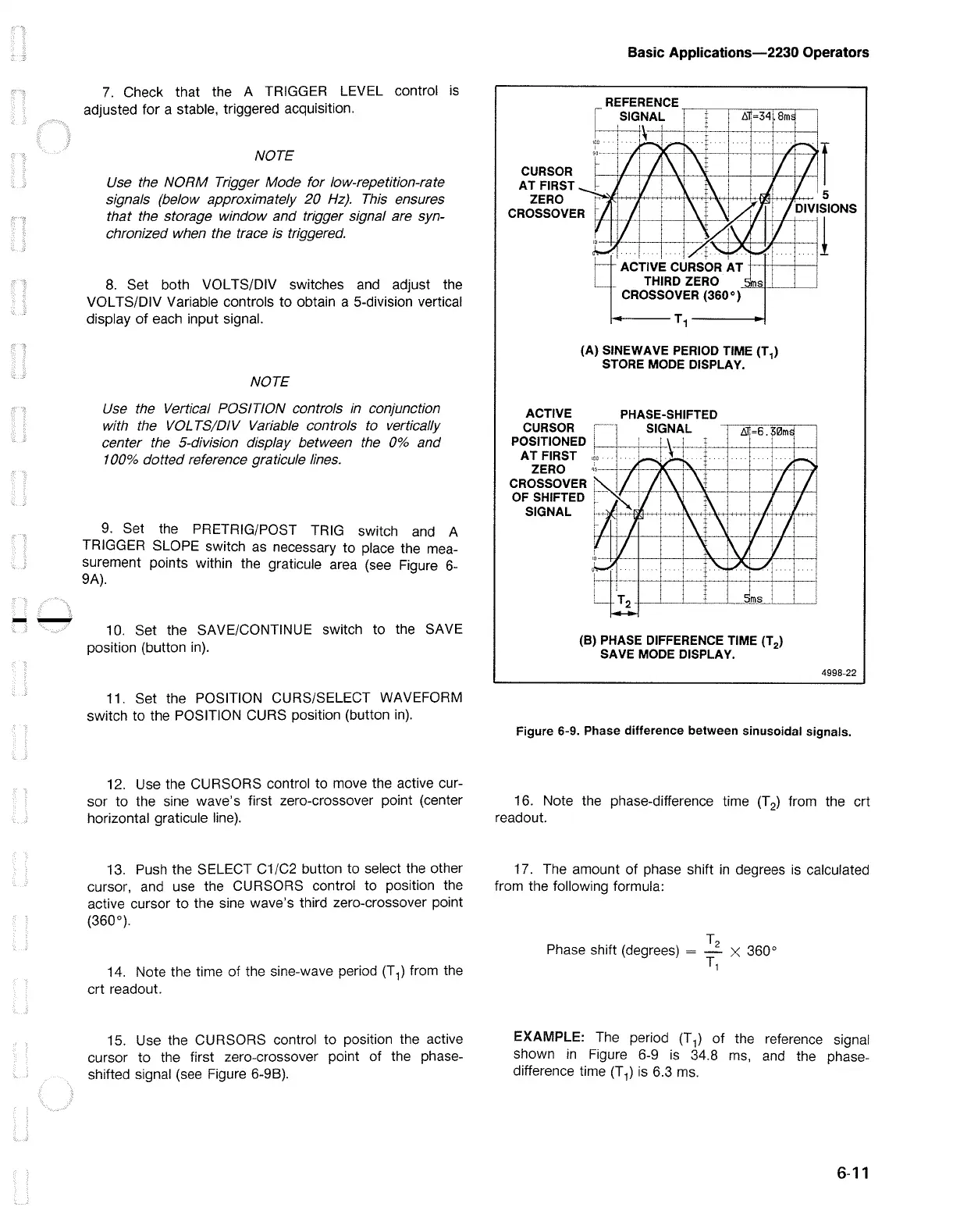
(A) SINEWAVE PERIOD TIME
(T
1
)
STORE MODE DISPLAY.
PHASE-SHIFTED
SIGNAL
~----~
c--+-----+----+-1
\-+-
-~+~---
-+-----+------+-------+-----<
.
·r
(B) PHASE DIFFERENCE TIME
(T
2
)
SAVE MODE DISPLAY.
4998-22
Figure 6-9. Phase difference between sinusoidal signals.
16. Note the phase-difference time
(T
2
) from the crt
readout.
17. The amount of phase shift
in
degrees
is
calculated
from the following formula:
T2
Phase shift (degrees) = - x 360°
T,
EXAMPLE:
The period
(T
1
)
of
the reference signal
shown
in
Figure 6-9
is
34.8
ms,
and the phase-
difference time
(T
1
)
is
6.3
ms.
6-11

 Loading...


