--
Basic Applications-2230 Operators
MAKING DIGIT AL STORAGE MEASUREMENTS
The following procedures will enable the operator to
perform some basic measurements and familiarize the
operator with digital storage measurement techniques.
Ac Peak-To-Peak Voltage Using Cursors
NOTE
Either channel input connector may be used for the
signal input. Use the VERTICAL MODE switches to
select the appropriate channel for display.
1 . Preset instrument controls and obtain a baseline
trace.
2.
Set the STORE/NON STORE switch to the STORE
position (button
in).
3.
Select a VOL TS/DIV switch setting that gives the
desired vertical deflection.
4. Set the A SEC/DIV switch to display several cycles
of
the waveform.
5.
Two cursors are displayed on the waveform to
be
measured. The boxed cursor
is
the active (selected) cur-
sor.
6.
Set the POSITION CURS/SELECT WAVEFORM
switch to the POSITION CURS position (button
in).
7.
Use the CURSORS control to move the active cur-
sor to either peak of the waveform.
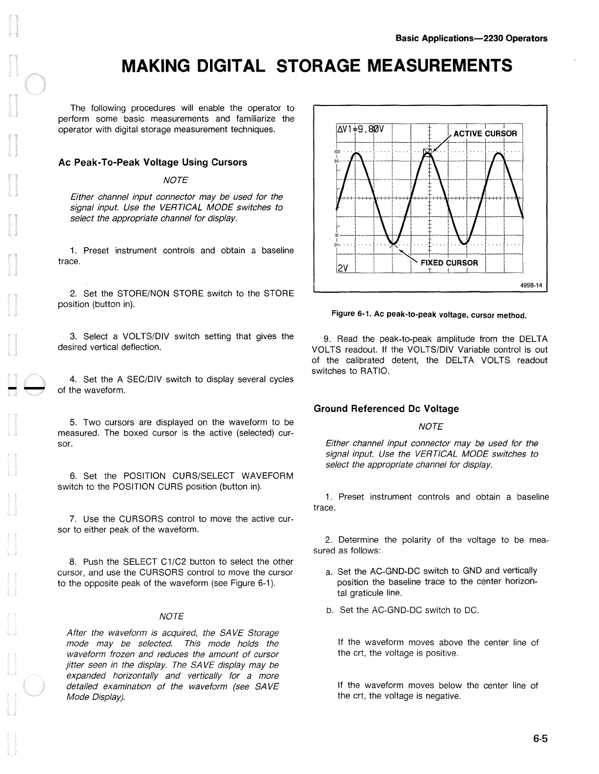
8.
Push the SELECT C1/C2 button to select the other
cursor, and use the CURSORS control to move the cursor
to
the opposite peak of the waveform (see Figure
6-1
).
NOTE
After the waveform is acquired, the
SA
VE
Storage
mode may be selected.
This
mode holds the
waveform frozen and reduces the amount
of
cursor
jitter seen
in
the display.
The
SA
VE
display may be
expanded horizontally and vertically for a more
detailed examination
of
the waveform
(see
SA
VE
Mode Display).
4998-14
Figure 6-1.
Ac
peak-to-peak voltage, cursor method.
9.
Read the peak-to-peak amplitude from the DEL TA
VOL TS readout. If the VOL TS/DIV Variable control is out
of
the calibrated detent, the DELTA VOL TS readout
switches to RATIO.
Ground Referenced De Voltage
NOTE
Either channel input connector may be used for the
signal input. Use the VERTICAL MODE switches to
select the appropriate channel tor display.
1 . Preset instrument controls and obtain a baseline
trace.
2.
Determine the polarity of the voltage to
be
mea-
sured
as
follows:
a.
Set the AC-GND-DC switch to GND and vertically
position the baseline trace to the center horizon-
tal graticule line.
b.
Set the AC-GND-DC switch to
DC.
If the waveform moves above the center line of
the crt, the voltage
is
positive.
If the waveform moves below the center line of
the crt, the voltage
is
negative.
6-5

 Loading...


