Basic Applications-2230 Operators
3.
Set the AC-GND-DC switch to GND and the
STORE/NON STORE switch to STORE mode (button
in).
If the channel signal is being used
as
the internal trigger
source, ensure that the TRIGGER Mode switch
is
set to
P-P AUTO.
4.
Use the appropriate channel Vertical POSITION con-
trol to move the baseline trace to a convenient reference
line. For example, if the voltage to
be
measured is positive,
position the baseline trace to the bottom graticule line; if
the voltage
is
negative, position the baseline trace to the
top graticule line; and if the voltage is
an
alternating sig-
nal, position the baseline trace to the center graticule line.
NOTE
If
the ground reference is set more than ± 5 divi-
sions from the center horizontal graticule
line,
the
ground reference will
not
be stored.
When
using
ADD VERTICAL MODE, both channel input coupling
switches must be
in
GND to store a ground refer-
ence.
5.
Set the selected channel AC-GND-DC switch to
DC.
An intensified ground reference dot
is
visible at the left
edge (the first sample location of the waveform display) of
the crt graticule.
NOTE
If
the vertical position
of
the display is moved after
the ground reference is stored, the displayed ground
reference is no longer a valid reference. Also, the
accuracy
of
the ground reference
is
affected by
de
offsets due to thermal drift and balance (DC and
INVERT) adjustments. Additionally,
if
the AC-GND-
DC switch is
set
to AC, the location
of
the ground
reference indicates the average value
of
the ac com-
ponent
of
a waveform.
6.
Set the POSITION CURS/SELECT WAVEFORM
switch to the POSITION CURS position (button
in).
7.
Use the CURSORS control to move the active cur-
sor to the ground reference point.
8.
Push the SELECT C1/C2 button to select the other
cursor. The nonmoving cursor
is
now the 0-volt reference
for making measurements
on
the waveform.
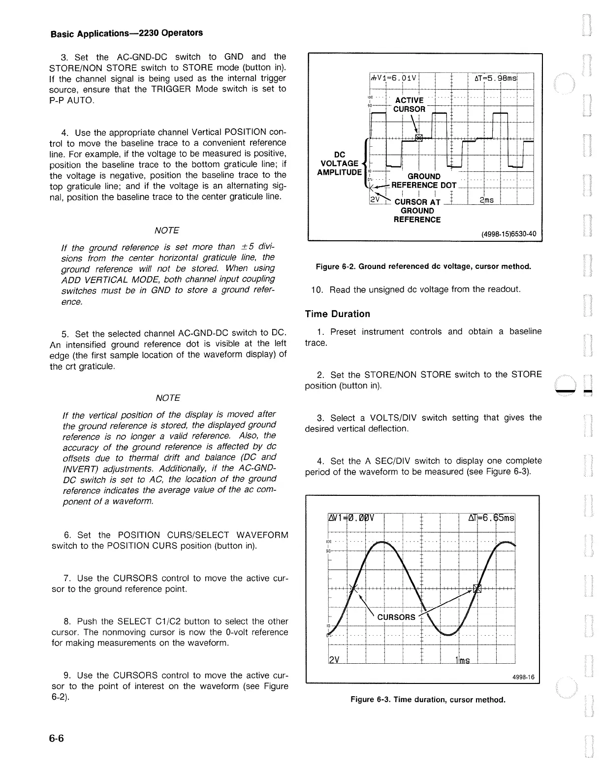
9.
Use the CURSORS control to move the active cur-
sor to the point
of
interest on the waveform (see Figure
6-2).
6-6
mV1=6.01V
l
lff=5.
9Bms
I
{4998-15)6530-40
Figure 6-2. Ground referenced de voltage, cursor method.
10. Read the unsigned
de
voltage from the readout.
Time Duration
1.
Preset instrument controls
and
obtain a baseline
trace.
2.
Set the STORE/NON STORE switch to the STORE
position (button
in).
3.
Select a VOL TS/DIV switch setting that gives the
desired vertical deflection.
4.
Set the A SEC/DIV switch to display one complete
period
of
the waveform to
be
measured (see Figure 6-3).
100
·
I
90-----+--+I--
~
Figure 6-3. Time duration, cursor method.
4998-16
--

 Loading...


