@)
--
@)
The
STORE mode display is the A Intensified
trace only.
The
intensified zone
on
the A trace
indicates the approximate delay position
and
length of the B Delayed Sweep.
The
displayed
position of the intensified zone is updated after
each
trigger. The A SEC/DIV, B SEC/DIV, and B
DELAY TIME POSITION settings
are
displayed
on the crt readout.
In
BOTH, STORE mode
acquisitions
are
controlled by the A SEC/DIV
switch.
B-Displays
either the
NON
STORE or the
STORE B Sweep trace. The A SEC/DIV, B
SEC/DIV,
and
B DELAY TIME POSITION settings
are
displayed
on
the crt readout, just
as
in
BOTH.
The
STORE mode waveform acquisitions are con-
trolled
by
the B SEC/DIV switch.
B
DELAY
TIME POSITION Control-Adjusts the
delay between the start time of the A Sweep
and
the
time that the B Sweep either starts (RUNS AFTER
DL
Y)
or
can
be
triggered (Triggerable After
Dly).
(The
A Sweep does not have to
be
displayed.)
The
delay
time
is
variable from 0.5 to 10 times the A SEC/DIV,
plus 300
ns.
In
Triggerable After Delay, the delay time readout
indicates the time that must elapse after the A
trigger before the delayed sweep or delayed acquisi-
tion
can
be
triggered; not the actual position of the
trigger point. However, the readout of the delay time
on
the crt follows the setting of the B DELAY TIME
POSITION control
in
either B Trigger
mode.
The
setting of the 1 K/4K switch affects the delay
time position setting for STORE mode displays
by
a
factor of approximately four times.
When
switching
between 1 K
and
4K record lengths, the delay time
position setting must
be
readjusted to obtain the
same delay time.
Horizontal
POSITION
Control-Positions
all
the
NON
STORE waveforms horizontally over a one-
sweep-length range (either
X1
or
X10
Magnified).
Using the Horizontal POSITION control, STORE
mode waveforms may
be
positioned over a range of
only
one
display window.
When
a STORE mode
acquisition display
is
longer than
one
screen
(as
in
4K records and/or
X10
MAG), the CURSORS POSI-
TION control
is
used
to position the display window
to
any
position of the acquisition record. The Hor-
izontal POSITION control does not position the crt
readout displays.
Controls, Connectors,
and
lndicators-2230 Operators
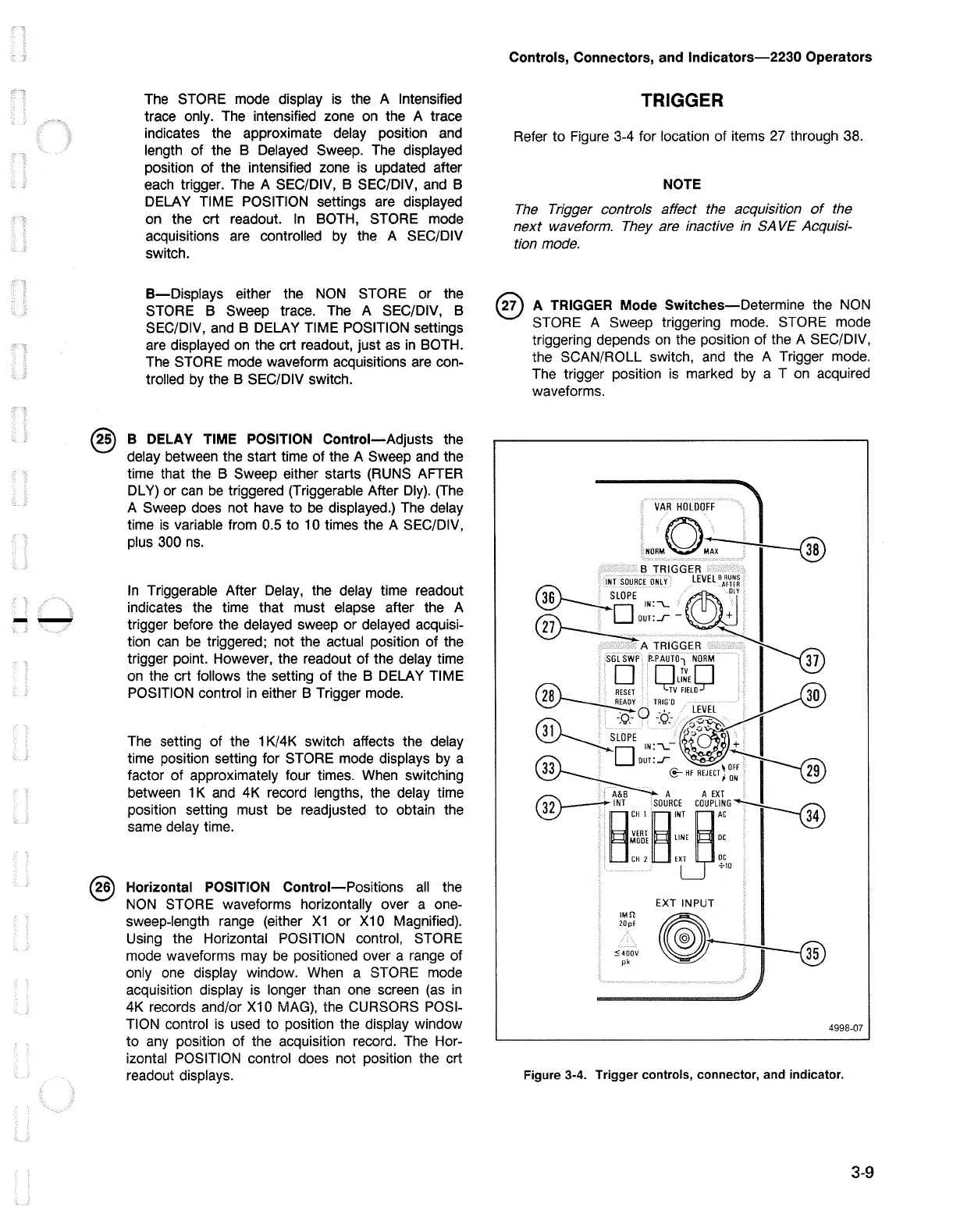
TRIGGER
Refer to Figure 3-4 for location of items
27
through 38.
NOTE
The
Trigger controls affect the acquisition
of
the
next
waveform. They are inactive
in
SA
VE
Acquisi-
tion mode.
@ A
TRIGGER
Mode
Switches-Determine
the
NON
STORE A Sweep triggering mode. STORE mode
triggering depends
on
the position of the A SEC/DIV,
the SCAN/ROLL switch,
and
the A Trigger mode.
The trigger position
is
marked by a T
on
acquired
waveforms.
""
""'"'ff
J
NORMO~
B TRIGGER
INT
SOURCE
ONL
y
LEVEL
\'rm
®----:LOPE
IN:""\_
ff1r\\
Oll
~ouT:_r-~
ATRIGGER
~
SGLSWP
P-PAUTOl
NORM.
JJ
• nTvn
Ld,LINE~
TV
FIELO
TRIG·o
_·
_ Q
_.,
,_
LEVEL
(ii\
s:~;E
,9~
O'
'{i:~ . I
~DIN:~
~,~
e-HF
REJECT}~~
I
~
A&B
A A
EXT
~
8
INT
CH
1
8
S0UR~!jCOUPL~~G--r--@
i~ii
LINE
OC
CH
2
EXT
OC
IM!l
20pf
:::4•
0V
pk
+10
EXT INPUT
@~
4998-07
Figure 3-4. Trigger controls, connector, and indicator.
3-9

 Loading...


