Options and
Accessories-2230
Operators
1.
Perform a serial poll.
2.
Send
an
EVENT? query to the oscilloscope
requesting service.
3.
If the EVENT? query response
is
not zero, then
perform the response required to handle the
event.
4.
Return to the main program.
OPTION 12 RS-232-C
OPERATORS INFORMATION
The RS-232-C Communications interface conforms to
the Tektronix standard
on
Codes, Formats, Conventions,
and
Features for messages sent over to bus for communi-
cations to other RS-232-C devices. Specific formats
implemented
in
the 2200
DSO
family for the Option
12
Communications interface are listed
in
Table 7
-7.
Specific
feature implementation
is
shown
in
Table 7-8.
Option 12 Side Panel
The side
panel
for Option
12
instruments (Figure 7-3)
includes one AUXILIARY connector, one RS-232-C inter-
face port (providing both
DTE
and
DCE
capability),
and
one PARAMETERS switch. The Controls, Connectors,
and
Indicators part of this manual contains information
on
the
use of the AUXILIARY Connector. Refer to Figure 7-3 for
location of the Option
12
side-panel controls
and
connectors.
AUXILIARY
Connector-Provides
connections for
an
X-Y
Plotter
and
an
External Clock input
(see
Controls, Con-
nectors,
and
Indicators).
RS-232-C PARAMETER Switch-Allows the selection of
setup options for the RS-232-C interface. The switches
are
read
at
power-up. Four sections of the switch select
the baud rate, three select parity,
one
selects the termi-
nator,
and
two
are
for printer/plotter selection.
The
function of
each
switch section
is
shown
in
Table 7 -11.
NOTE
Do not hook up external devices to the DTE connec-
tor and the DCE connector
at
the same
time.
7-10
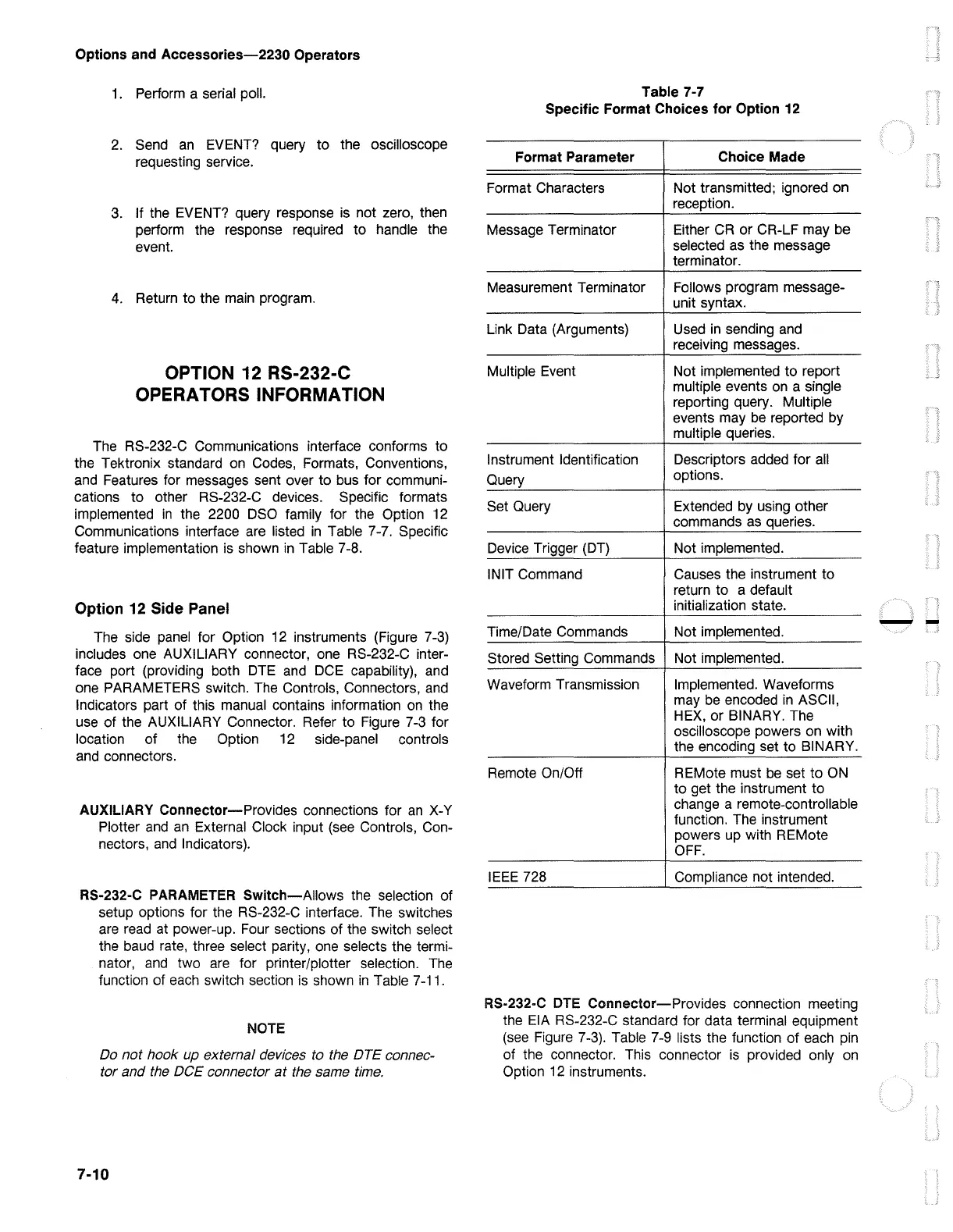
Table 7-7
Specific Format Choices for Option 12
Format Parameter
Choice Made
Format Characters
Not transmitted; ignored on
reception.
Message Terminator Either
CR
or CR-LF may be
selected as the message
terminator.
Measurement Terminator
Follows program message-
unit syntax.
Link Data (Arguments)
Used
in
sending
and
receiving messages.
Multiple Event Not implemented to report
multiple events
on
a single
reporting query. Multiple
events may
be
reported by
multiple queries.
Instrument Identification
Descriptors added for
all
Query
options.
Set Query
Extended
by
using other
commands
as
queries.
Device Trigger
(DT)
Not implemented.
INIT Command Causes the instrument to
return to a default
initialization state.
Time/Date Commands
Not implemented.
Stored Setting Commands
Not implemented.
Waveform Transmission Implemented. Waveforms
may
be
encoded
in
ASCII,
HEX,
or BINARY. The
oscilloscope powers on with
the encoding set to BINARY.
Remote On/Off REMote must
be
set to
ON
to get the instrument to
change a remote-controllable
function. The instrument
powers up with REMote
OFF.
IEEE
728 Compliance not intended.
RS-232-C
DTE
Connector-Provides connection meeting
the
EIA
RS-232-C standard for data terminal equipment
(see
Figure 7-3). Table 7-9 lists the function of each
pin
of the connector. This connector
is
provided only
on
Option
12
instruments.
--

 Loading...


