--
NOTE
The
intensified zone seen
in
the
ALT
HORIZONTAL
MODE display will move from trigger point to trigger
point as the B DELAY TIME POSITION control is
rotated.
2.
Adjust the B TRIGGER LEVEL control so the
intensified zone
on
the A trace
is
stable.
3.
The apparent magnification factor
can
be
calculated
from the formula shown
in
step 8 of the "Magnified Sweep
Runs After Delay" procedure.
DELA YEO-SWEEP TIME MEASUREMENTS
Operating the instrument with HORIZONTAL MODE set
to
either ALT or B permits time measurements to
be
made
with a greater degree of accuracy than attained with HOR-
IZONTAL MODE set to
A.
The following procedures
describe how these measurements
are
accomplished.
Time Difference Between Repetitive Pulses
1 . Preset instrument controls
and
obtain a baseline
trace.
2.
Turn the Readout
ON
if it's not
on
already.
3.
Apply the signal to either vertical-channel input con-
nector
and
set the VERTICAL MODE switch to display the
channel used.
4.
Set
the
appropriate VOL TS/DIV switch to produce a
display of approximately 2 or 3 divisions
in
amplitude.
5.
Set the A SEC/DIV switch to display the measure-
ment points of interest within the graticule area.
6.
Select BOTH HORIZONTAL MODE
and
adjust both
the appropriate channel POSITION control
and
A/8 SWP
SEP control to display the A trace above the B trace.
7.
For the most accurate measurement, set the B
SEC/DIV switch
to
the fastest sweep speed that provides
a usable (visible) intensified zone.
8.
Adjust the B DELAY TIME POSITION control to
move the intensified zone to the leading edge of the first
Basic Applications-2230 Operators
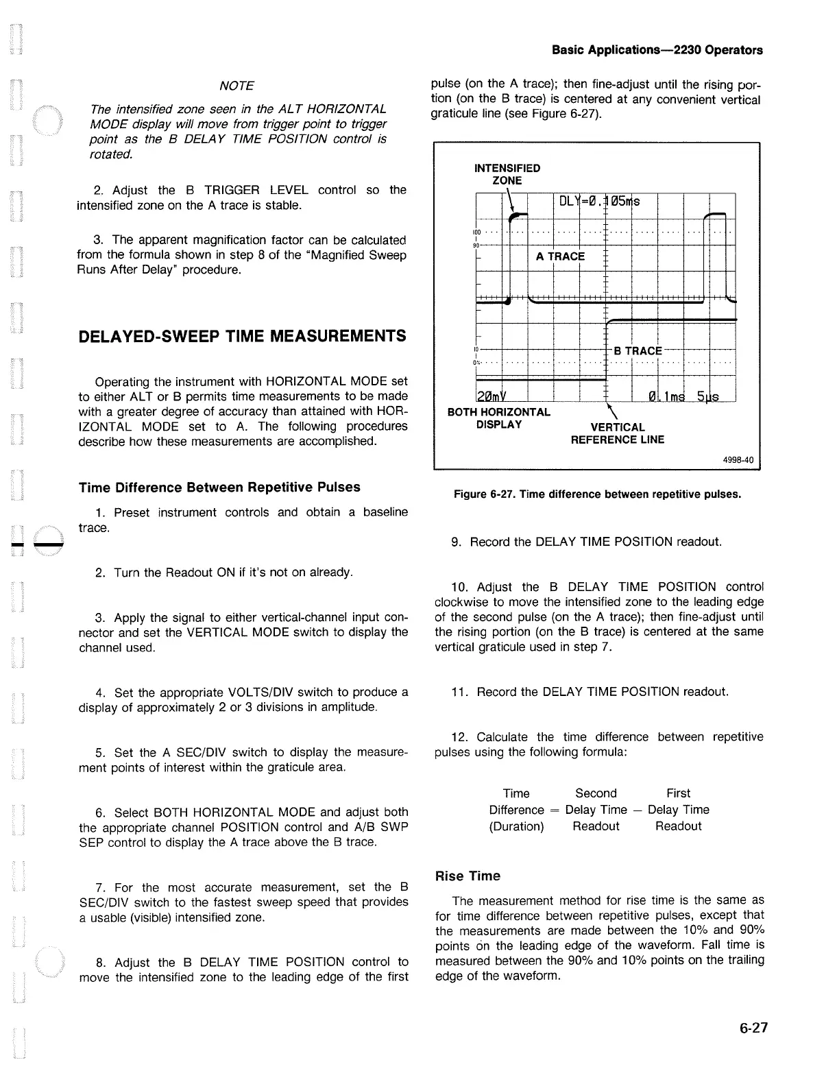
pulse
(on
the A trace); then fine-adjust until the rising por-
tion
(on
the B trace)
is
centered at any convenient vertical
graticule line
(see
Figure 6-27).
INTENSIFIED
ZONE
I
\
..:-.
I
100
•
....
.
..
I
90
DL~
=0.
ff05n
s
.. ..
...
. .
...
. . .
A TRACE
---
~
IO
I
r-·
l?(,ll..,,
HORIZONTAL BOTH
DISPLAY
B TRACE
c;l]
\
VERTICAL
REFERENCE LINE
1
MC
-
-
s,
Ii::
4998-40
Figure 6-27. Time difference between repetitive pulses.
9.
Record the DELAY TIME POSITION readout.
10. Adjust the B DELAY TIME POSITION control
clockwise to move the intensified zone to the leading edge
of the second pulse
(on
the A trace); then fine-adjust until
the rising portion
(on
the B trace)
is
centered at the same
vertical graticule used
in
step
7.
11. Record the DELAY TIME POSITION readout.
12. Calculate the time difference between repetitive
pulses using the following formula:
Time Second First
Difference = Delay Time - Delay Time
(Duration) Readout Readout
Rise Time
The measurement method for rise time
is
the same
as
for time difference between repetitive pulses, except that
the measurements are made between the 10%
and
90%
points
on
the leading edge of the waveform.
Fall
time
is
measured between the 90%
and
10% points
on
the trailing
edge of the waveform.
6-27

 Loading...


