Basic Applications-2230 Operators
1.
Preset instrument controls
and
obtain a baseline
trace.
2.
Apply a 5-division signal to either vertical-channel
input connector
and
set the VERTICAL MODE switch to
display the channel used. Ensure that the VOL TS/DIV
Variable control
is
in
the CAL detent.
NOTE
For rise times less than 0.2 µs
per
division, the
VOL
TS/DIV Variable control may be used to obtain
an exact 5-division display.
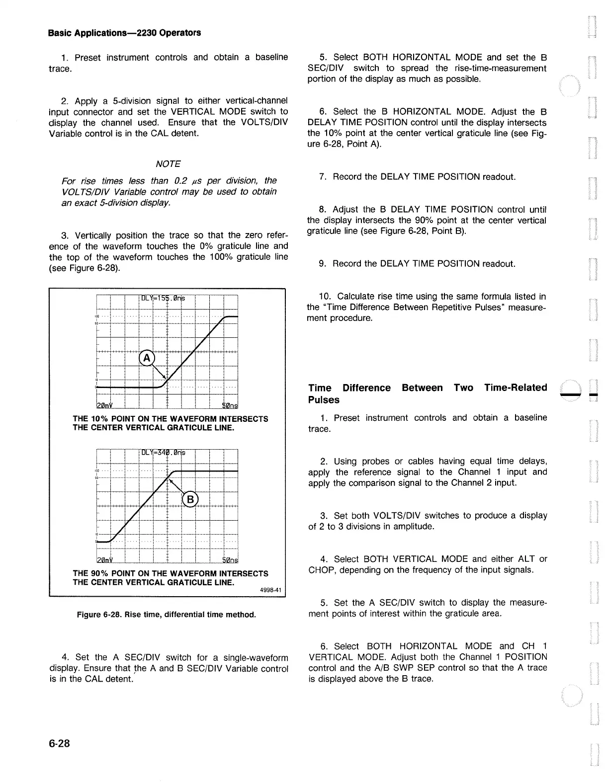
3. Vertically position the trace so that the zero refer-
ence of the waveform touches the 0% graticule line
and
the top of the waveform touches the 100% graticule line
(see Figure 6-28).
ULY
=1!:>
•
l!Jr
is
i
I
1~0
j
-
I
,0
V
T
V
i\.A
V
~
/
'°
I
-'!
I
r
l?OIM'~
'i0ns
THE
10%
POINT ON THE WAVEFORM INTERSECTS
THE CENTER VERTICAL GRATICULE LINE.
THE
90%
POINT ON THE WAVEFORM INTERSECTS
THE CENTER VERTICAL GRATICULE LINE.
4998-41
Figure 6-28. Rise time, differential time method.
4.
Set the A SEC/DIV switch for a single-waveform
display. Ensure that the A
and
B SEC/DIV Variable control
is
in
the CAL detent.
6-28
5.
Select BOTH HORIZONTAL MODE
and
set the B
SEC/DIV switch
to
spread the rise-time-measurement
portion of the display
as
much
as
possible.
6.
Select the B HORIZONTAL MODE. Adjust the B
DELAY TIME POSITION control until the display intersects
the 10% point at the center vertical graticule line (see Fig-
ure 6-28, Point
A).
7.
Record the DELAY TIME POSITION readout.
8.
Adjust the B DELAY TIME POSITION control until
the display intersects the 90% point at the center vertical
graticule line (see Figure 6-28, Point
B).
9.
Record the DELAY TIME POSITION readout.
10. Calculate rise time using the same formula listed
in
the "Time Difference Between Repetitive Pulses" measure-
ment procedure.
Time Difference Between Two Time-Related
Pulses
1.
Preset instrument controls
and
obtain a baseline
trace.
2.
Using probes or cables having equal time delays,
apply the reference signal to the Channel 1 input
and
apply the comparison signal to the Channel 2 input.
3.
Set both VOL TS/DIV switches to produce a display
of 2 to 3 divisions
in
amplitude.
4.
Select BOTH VERTICAL MODE
and
either ALT or
CHOP, depending on the frequency of the input signals.
5.
Set the A SEC/DIV switch to display the measure-
ment points of interest within the graticule area.
6.
Select
BOTH
HORIZONTAL MODE
and
CH
1
VERTICAL MODE. Adjust both the Channel 1 POSITION
control
and
the A/B SWP
SEP
control so that the A trace
is displayed above the B trace.
--

 Loading...


