--
DL
=0.
55
s
I
. CHANNEL 1 (REFERENCE)
!00
.
.
...
I
t I
90
± I
~
INTENSIFIED
\.
ZONE
>-
>-
Yi:'
IO
,_
B TRACE FOR -
~
I
CHANNEL 1
0¼·
.
I
I I I
50m' 0
1m
51
s
t
VERTICAL REFERENCE LINE
t
DL'
=0.
55m~
._
_c---
I
y
100
·
....
F""--:..
-
I
90
~
-
INTENSIFIED -
ZONE
-
I
+
f++++-
H-CHANNEL 2
>-
>-
10
- B TRACE FOR
-
I
CHANNEL 2
0¾·
.
I I I I
~
7V
fi'I
1
...
J
c;,
C,
4998-42
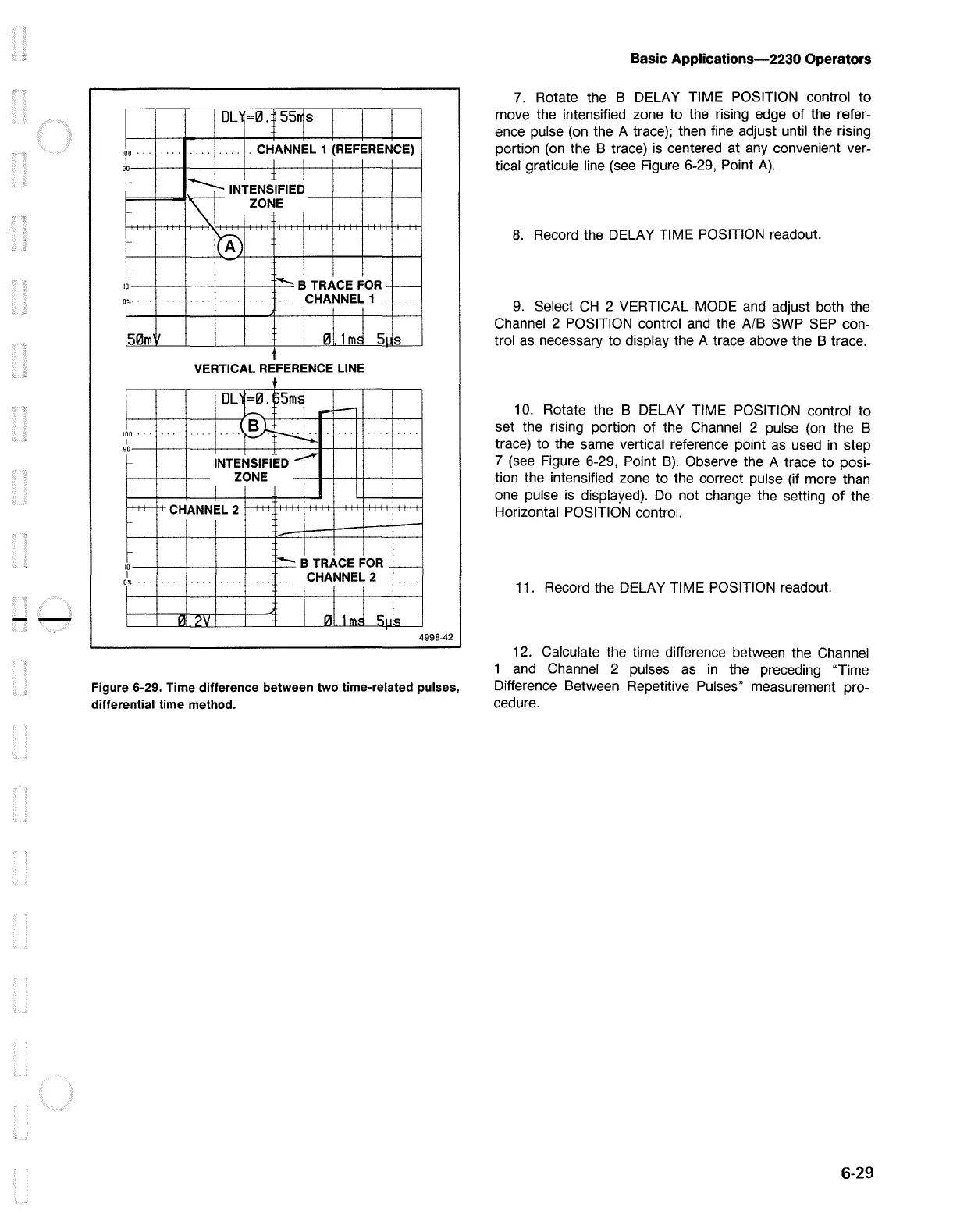
Figure 6-29. Time difference between two time-related pulses,
differential time method.
Basic Applications-2230 Operators
7.
Rotate the B DELAY TIME POSITION control to
move the intensified zone to the rising edge of the refer -
ence pulse
(on
the A trace); then fine adjust until the rising
portion
(on
the B trace)
is
centered at any convenient ver-
tical graticule line
(see
Figure 6-29, Point
A).
8.
Record the DELAY TIME POSITION readout.
9.
Select
CH
2 VERTICAL MODE
and
adjust both the
Channel 2 POSITION control
and
the
A/8
SWP
SEP
con-
trol
as
necessary to display the A trace above the B trace.
10.
Rotate the B DELAY TIME POSITION control to
set the rising portion of the Channel 2 pulse
(on
the B
trace) to the same vertical reference point
as
used
in
step
7
(see
Figure 6-29, Point
B).
Observe the A trace to posi-
tion the intensified zone to the correct pulse (if more than
one pulse
is
displayed).
Do
not change the setting
of
the
Horizontal POSITION control.
11. Record the DELAY TIME POSITION readout.
12.
Calculate the time difference between the Channel
1
and
Channel 2 pulses
as
in
the preceding "Time
Difference Between Repetitive Pulses" measurement pro-
cedure.
6-29

 Loading...


