Preparation for
Use-2230
Operators
Plug Line
Reference
Configuration
Usage
Voltage
Standards
'~
North
ANSI
C73.11
American
120V
NEMA
5-15-P
120V/
IEC
83
15A
~
Universal
Euro
240V
CEE (7).11,IV,VII
240V/
IEC
83
10-16A
~
UK
BS
1363
it
240V/
240V
IEC
83
13A
~
Australian
240V/
240V
AS
C112
10A
~
North
ANSI
C73.20
~)
'
American
240V
NEMA
6-15-P
240V/
IEC
83
.•
0
15A
~
Switzerland
11/,,/''-.
---
220V/
220V
SEV
'"'_/----..~
6A
Abbreviations:
ANSI
-
American
National
Standards
Institute
AS
-
Standards
Association
of
Australia
BS
-
British
Standards
Institution
CEE -
International
Commission
on
Rules
for
the
Approval
of
Electrical
Equipment
IEC -
International
Electrotechnical
Commission
NEMA
-
National
Electrical
Manufacturer's
Association
SEV
-
Schweizevischer
Elektrotechischer
Verein
(2931-21 )4204-53
Figure 2-2. Optional power-cord data.
LINE FUSE
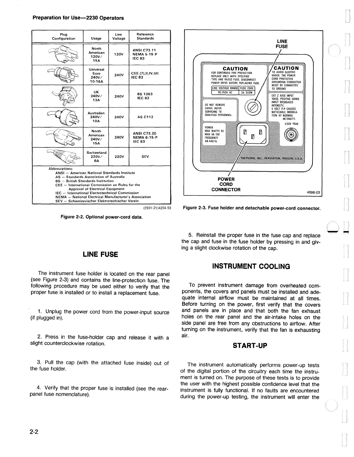
The
instrument fuse holder
is
located
on
the rear
panel
(see
Figure
2-3)
and
contains the line-protection fuse.
The
following procedure
may
be
used
either to verify that the
proper fuse
is
installed or to install a replacement
fuse.
1.
Unplug the power cord from the power-input source
(if plugged
in).
2.
Press
in
the fuse-holder cap
and
release it with a
slight counterclockwise rotation.
3.
Pull
the cap (with the attached fuse inside) out of
the fuse holder.
4.
Verify that the proper fuse
is
installed
(see
the rear-
panel fuse nomenclature).
2-2
CAUTION
FOR
CONTINUED
FIRE
PROTECTION
REPLACE
ONLY
WITH
SPECIFIED
TYPE
ANO
RATED
FUSE.
OISCONNECT
POWER
INPUT
BEFORE
REPLACING
FUSE.
LINE
VOLTAGE
RANGE
FUSE
250V
90-250V
AC
00
NOT
REMOVE
COVER.
REFER
SERVICING
TO
OUALIFIED
PERSONNEL
POWER
MAX
WATTS
85
POWER
CORD
CONNECTOR
2A
SLOW
LINE
FUSE
EXT
Z
AXIS
INPUT
10Kn.
POSITIVE
GOING
INPUT
DECREASES
INTENSITY.
5
VOLT
P-P
CAUSES
NOTICEABLE
MODULA-
TION
AT
NORMAL
INTENSITY.
530V
PEAK
4998-03
Figure 2-3. Fuse holder and detachable power-cord connector.
5.
Reinstall the proper fuse
in
the fuse cap
and
replace
the cap
and
fuse
in
the fuse holder by pressing
in
and
giv-
ing
a slight clockwise rotation of the cap.
INSTRUMENT COOLING
To
prevent instrument damage from overheated com-
ponents, the covers
and
panels must
be
installed
and
ade-
quate internal airflow must
be
maintained at
all
times.
Before turning
on
the power, first verify that the covers
and
panels
are
in
place
and
that both the
fan
exhaust
holes
on
the rear
panel
and
the air -intake holes
on
the
side
panel
are
free from
any
obstructions to airflow. After
turning
on
the instrument, verify that the
fan
is
exhausting
air.
START-UP
The
instrument automatically performs power-up tests
of
the digital portion of the circuitry each time the instru-
ment
is
turned
on.
The
purpose of these tests
is
to provide
the user with the highest possible confidence
level
that the
instrument
is
fully functional. If no faults are encountered
during the power-up testing, the instrument will enter the
--

 Loading...


