Basic Applications-2230 Operators
TIME POSITION control. With either BOTH or B HOR-
IZONTAL MODE selected, the B DELAY TIME POSITION
control provides continuously variable positioning of the B
Sweep. The range of this control is sufficient to place the
B Sweep interval at any location within the A Sweep inter-
val. When BOTH HORIZONTAL MODE
is
selected, the B
SEC/DIV switch setting determines the B Sweep speed
and concurrently sets the length of the intensified zone
on
the A trace.
Using delayed-sweep magnification may produce a
display with some slight horizontal movement (pulse jitter).
Pulse jitter includes not only the inherent uncertainty of
triggering the delayed sweep at exactly the same trigger
point each time, but also jitter that may
be
present
in
the
input signal. If pulse jitter needs to
be
measured, use the
"Pulse Jitter Time Measurement" procedure.
Magnified Sweep
Runs
After Delay
The following procedure explains how to operate the B
Sweep
in
a nontriggered mode and to determine the
resulting apparent magnification factor.
1.
Preset instrument controls and obtain a baseline
trace.
2.
Apply the signal to either vertical channel input con-
nector and set the VERTICAL MODE switch to display the
channel used.
3.
Set the appropriate VOL TS/DIV switch to produce a
display of approximately 2 or 3 divisions
in
amplitude
and
center the display.
4.
Set the A SEC/DIV switch to a sweep speed which
displays at least one complete waveform cycle.
5.
Select BOTH HORIZONTAL MODE. Adjust both the
appropriate channel POSITION control and the A/B SWP
SEP control to display the A trace above the B trace.
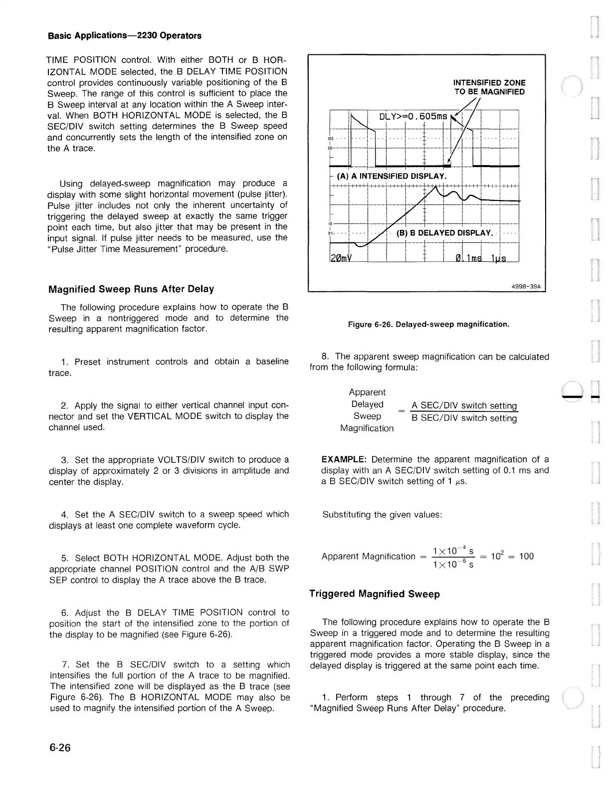
6.
Adjust the B DELAY TIME POSITION control to
position the start of the intensified zone to the portion of
the display to
be
magnified (see Figure 6-26).
7.
Set the B SEC/DIV switch to a setting which
intensifies the full portion of the A trace to
be
magnified.
The intensified zone will
be
displayed
as
the B trace
(see
Figure 6-26). The B HORIZONTAL MODE may also
be
used to magnify the intensified portion of the A Sweep.
6-26
INTENSIFIED ZONE
TO
BE
MAGNIFIED
~~~A--.---,---;
4998-39A
Figure 6-26. Delayed-sweep magnification.
8.
The apparent sweep magnification
can
be
calculated
from the following formula:
Apparent
Delayed
Sweep
Magnification
A SEC/DIV switch setting
B SEC/DIV switch setting
EXAMPLE: Determine the apparent magnification of a
display with
an
A SEC/DIV switch setting of
0.1
ms
and
a B SEC/DIV switch setting of 1
µs.
Substituting the given values:
1
x10
4
s
Apparent Magnification =
--'---'----
= 10
2
= 100
1X10
6
s
Triggered Magnified Sweep
The following procedure explains how to operate the B
Sweep
in
a triggered mode
and
to determine the resulting
apparent magnification factor. Operating the B Sweep
in
a
triggered mode provides a more stable display, since the
delayed display
is
triggered at the same point each time.
1 . Perform steps 1 through 7 of the preceding
"Magnified Sweep Runs After Delay" procedure.
--

 Loading...


