General
lnformation-2230
Operators
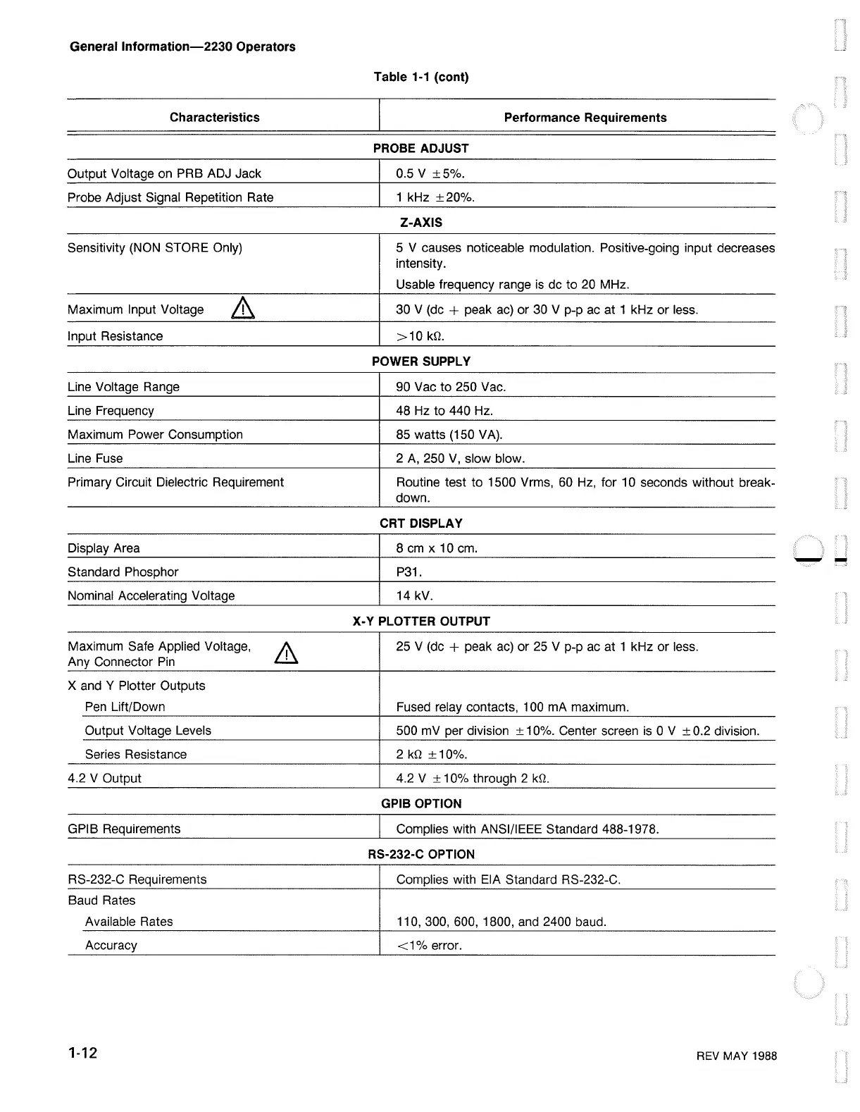
Characteristics
Output Voltage
on
PRB ADJ Jack
Probe Adjust Signal Repetition Rate
Sensitivity
(NON
STORE Only)
Maximum Input Voltage
Input Resistance
Line Voltage Range
Line Frequency
Maximum Power Consumption
Line
Fuse
Primary Circuit Dielectric Requirement
Display Area
Standard Phosphor
Nominal Accelerating Voltage
Maximum Safe Applied Voltage,
'I'
Any Connector
Pin
l..!J.
X and Y Plotter Outputs
Pen
Lift/Down
Output Voltage Levels
Series Resistance
4.2 V Output
GPIB Requirements
RS-232-C Requirements
Baud Rates
Available Rates
Accuracy
1-12
Table 1-1 (cont)
Performance Requirements
PROBE ADJUST
0.5 V
±5%.
1 kHz
±20%.
Z-AXIS
5 V causes noticeable modulation. Positive-going input decreases
intensity.
Usable frequency range is de to
20
MHz.
30 V
(de
+ peak
ac)
or 30 V p-p
ac
at 1 kHz or less.
>10
kQ.
POWER SUPPLY
90 Vac to 250 Vac.
48
Hz
to 440
Hz.
85 watts (150 VA).
2
A,
250
V,
slow blow.
Routine test to 1500 Vrms,
60
Hz,
for 10 seconds without break-
down.
CRT DISPLAY
8cmx10cm.
P31.
14 kV.
X-Y PLOTTER OUTPUT
25
V
(de
+ peak
ac)
or
25
V p-p ac at 1 kHz or less.
Fused relay contacts, 100 mA maximum.
500 mV per division ± 10%. Center screen
is
O V ± 0.2 division.
2
kQ
±10%.
4.2 V ± 10% through 2
kQ.
GPIB OPTION
Complies with ANSI/IEEE Standard 488-1978.
RS-232-C OPTION
Complies with EIA Standard RS-232-C.
110, 300, 600, 1800,
and
2400 baud.
<1%
error.
REV
MAY 1988
--

 Loading...


