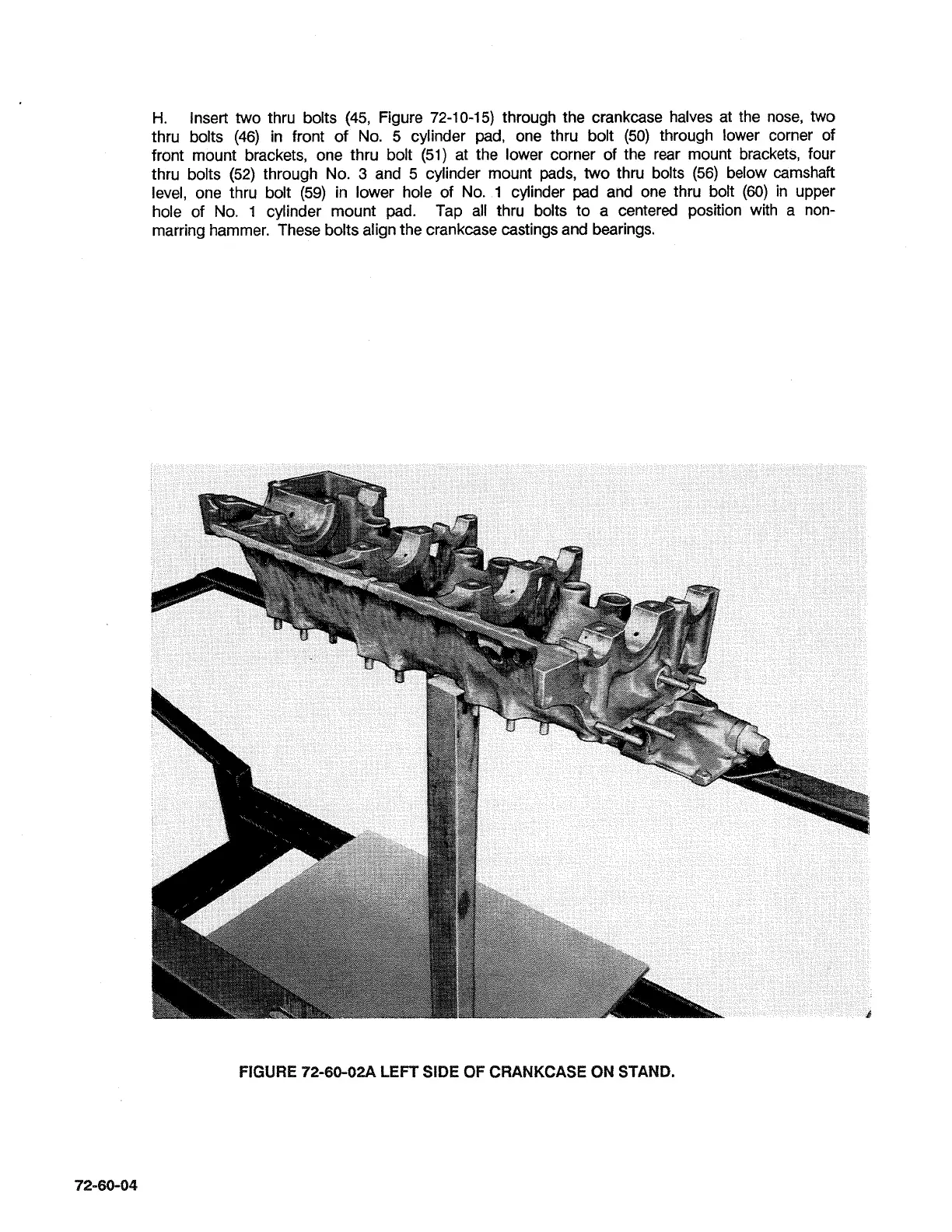
H.
Insert two thru bolts (45, Figure 72-10-15) through the crankcase halves at the nose, two
thru bolts (46) in front of No. 5 cylinder pad, one thru bolt (50) through lower corner of
front mount brackets, one thru bolt (51) at the lower corner of the rear mount brackets, four
thru bolts (52) through No.
3
and 5 cylinder mount pads, two thru bolts (56) below camshaft
level, one thru bolt (59) in lower hole of No.
1
cylinder pad and one thru bolt
(60)
in upper
hole of No. 1 cylinder mount pad. Tap all thru bolts to a centered position with a
non-
marring hammer. These bolts align the crankcase castings and bearings.
FIGURE 72-60-02A LEFT SIDE
OF
CRANKCASE
ON
STAND.
 Loading...

