10 Fire Panel IRIS - Installation Manual
IMPORTANT:
The relay of the respective programmable output only breaks the circuit (NC: The left termi-
nal lead) or closes the circuit (NO: The right terminal lead) according to the middle lead of
each terminal.
The relays of the programmable outputs just open or close the output circuit – there is no
difference in the potentials between the separate terminal leads!
At the monitored outputs Sounder, Fire Protection, Fire and Fault could be measured 24 VDC
and maximum output current 0,5A at closed relay contacts, ad 0V at open relay contacts.
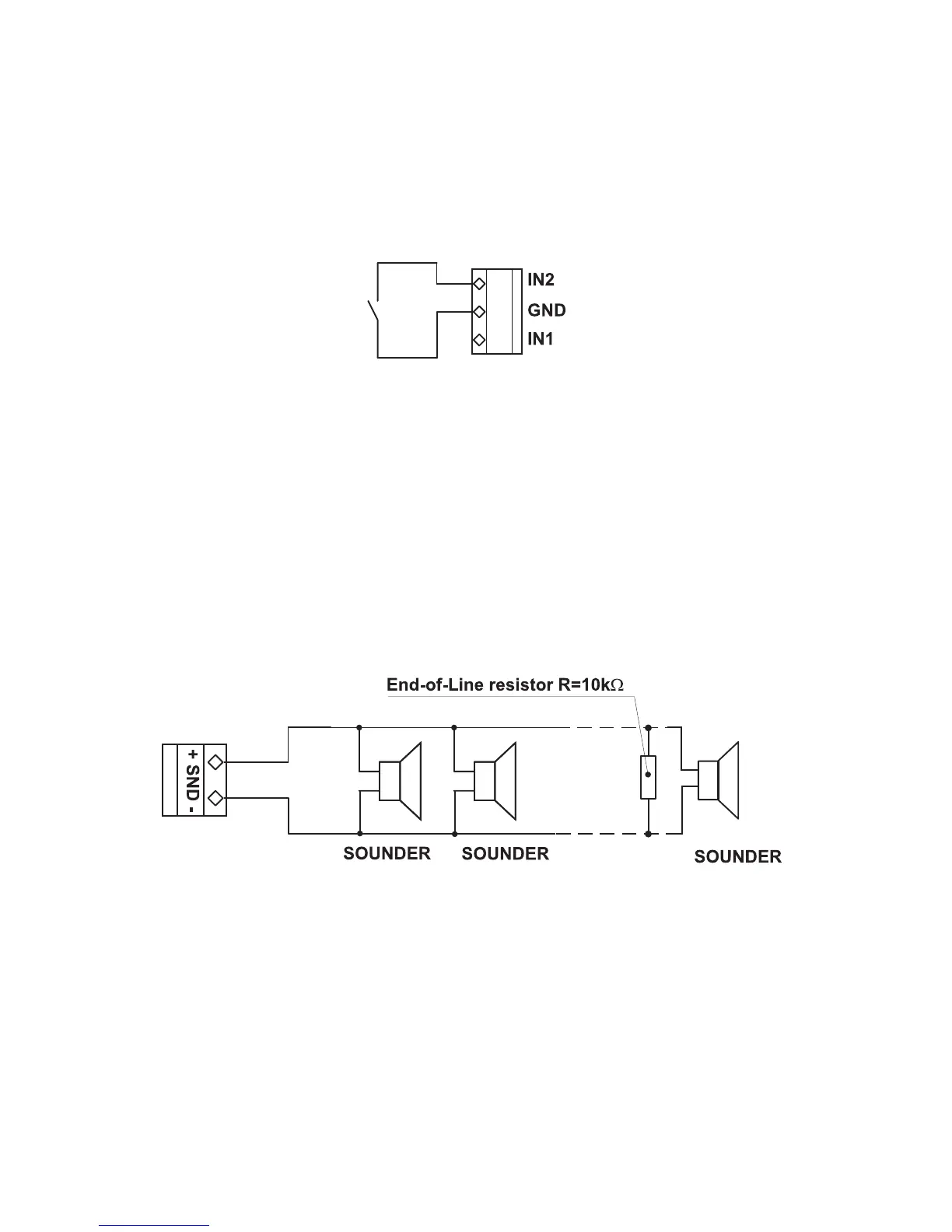
Figure 12 – Example for connecting
a button to inputs IN1 and IN2.
ATTENTION:
The active level of the input signal is logical zero!
To the monitored output Sounder could be connected several sounders – Figure 13. The maximum number
of sounders that could be connected in the circuit, depends on their total current consumption, which must
not exceed 0,5A.
Before connecting the last sounder in the circuit, parallel to it must be added end-of-line resistor 10k.
Figure 13. Connecting of sounders.