Fire Panel IRIS - Installation Manual 13
2.2.6 Maximum permissible cable length
The maximum length of the loop in the system could vary according to the cross-section and the ohmic resist-
ance of the used cable. To make possible identifying devices with identical addresses (double addresses) in
the system configuration, the cable resistance should not exceed definite calculated value. According to the
ohmic cable resistance, calculate:
· Formula 1: L
C1MAX
= 21 / R
C
· Formula 2: L
C2MAX
= 80 / R
C
,
Where:
L
C1MAX
and L
C2MAX
- are maximum permissible length of the used cabel, [km];
R
C
- is total ohmic resistance of the two wires of the used able; its value shows the magnitude of the cable
resistance at length 1km [Ω/km].
If L
C
is the necessary length of the cable used in the loop, then:
· At L
C
≤ L
C1MAX
- the fire pane will be able to communicate with the devices in the circuit and also will
be able to identify the presence of double address.
· At L
C1MAX
< L
C
≤ L
C2MAX
- the fire panel will be able to communicate with the devices in the circuit
but will not be able to identify the presence of double addresses.
· At L
C
> L
C2MAX
- the fire panel will not be able neither to communicate with the devices nor to identify
the presence of double addresses.
Example:
R
C
= 39 Ω/km, then
L
C1MAX
= 21 / RC = 21 / 39 ≈ 0,540km
L
C2MAX
= 80 / RC = 80 / 39 ≈ 2km
L
C
= 1km
In this case it is possible to use the chosen cable in the system, but the fire panel will not be able to identify
devices with double addresses. If this could not satisfying the requirements of the system it must be chosen
cable with lower ohmic resistance RC.
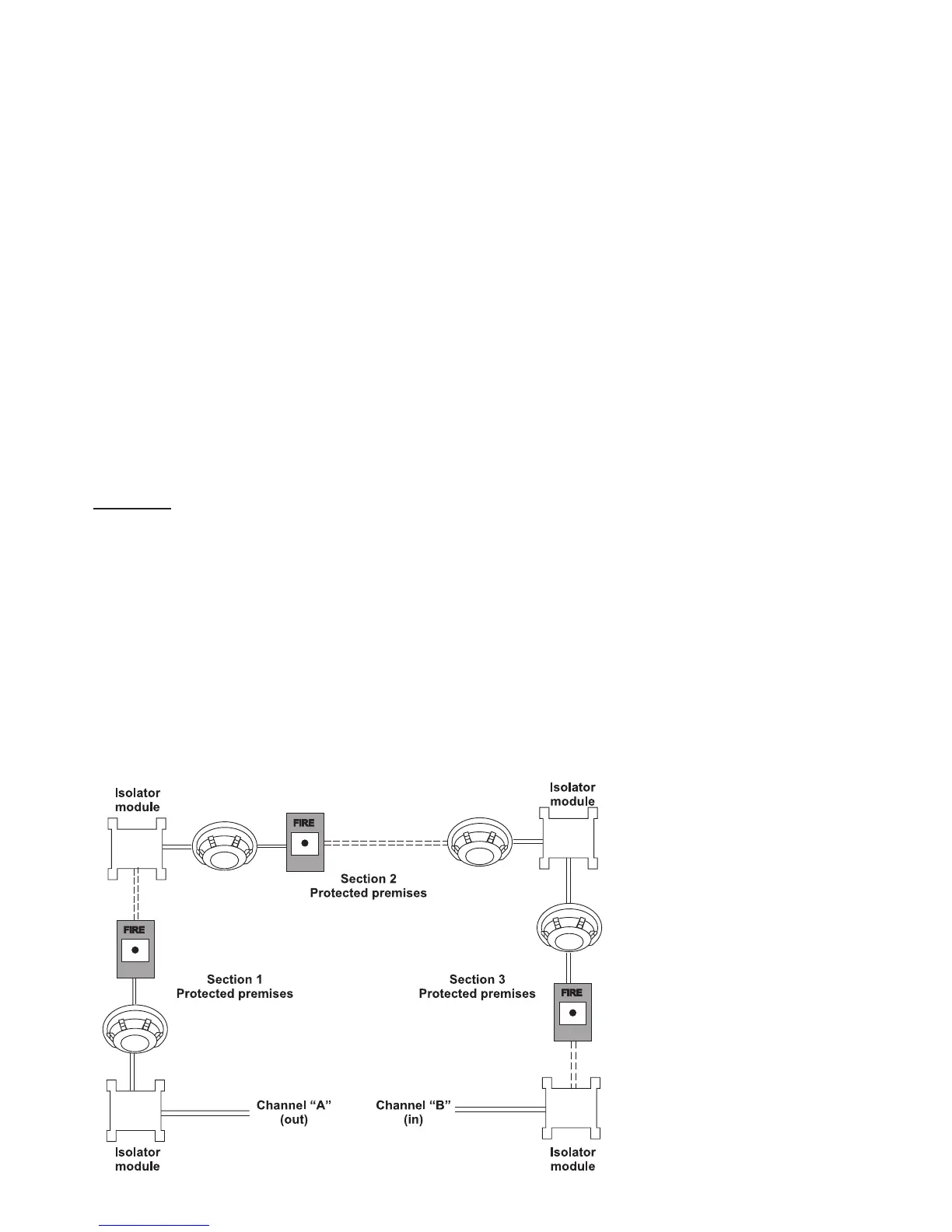
The connection diagram shown on Figure 18, gives the possibility to protect devices against opening and
short-circuit. For example, short-circuit in section 2 will not influence the operation of sections 1 and 3. The
isolator modules at the both ends of section 2 will isolate it, and section 1 and 3 will continue working properly,
as section 1 will operate by supply from the channel “A” and section 3 – by supply from channel “B”. Since
the fire panel will not be able to communicate with the devices from section 2, it will generate an alarm signal
for lost devices and open circuit.
Figure 18.
IMPORTANT
:
The maximum number of
devices between two iso-
lator modules is 30!