Fire Panel IRIS - Installation Manual 11
2.2.4 20 Relay Expander Module
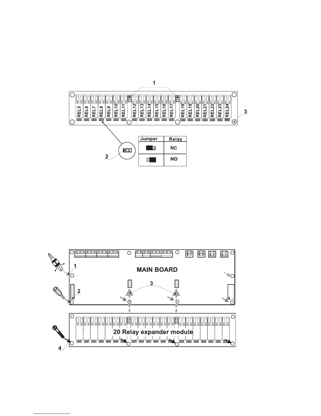
20 Relay Expander Module (Figure 14.) is an additional module by which the total number of the program-
mable outputs increases to 24. The expander consists of 20 relays, controlling 20 separate outputs (110V /
1A) – numbered REL5 – REL24.
The function of the relays is just to open or close the output circuit according to their configuration (the posi
-
tion of the jumper).
It is possible the relay of the respective programmable output to open the circuit (NC: the left terminal lead)
or to close it (NO: the right terminal lead) according to the middle lead of each terminal.
Figure 14. General view of 20 Relay Expander Module.
• REL5 – REL24 – Programmable outputs, 110V / 1A;
• NC - Normally closed contact;
• NO - Normally open contact;
1 - Flat interface connectors for connecting 20 Relay expander module to the Main board;
2 - Jumper leads for programming the function of the respective relay – to open (NC) or to
close (NO) the circuit;
3 - Mounting holes for fixing the 20 Relay expander module to the Main board.
Adding of 20 Relay Expander Module to the Main Board of the fire panel
Figure 15.
1 – Place the mounting clips into the pointed holes, as shown on Figure 15.
2 – Screw the mounting supports into the pointed holes, as shown on Figure 15.
3 – Place 20 Relay expander module on the Main board, thus the flat interface connectors
on the both PCBs to connect to each other.
4 – Fix with suitable bolts 20 Relay expander module to the Main Board.