14 Fire Panel IRIS - Installation Manual
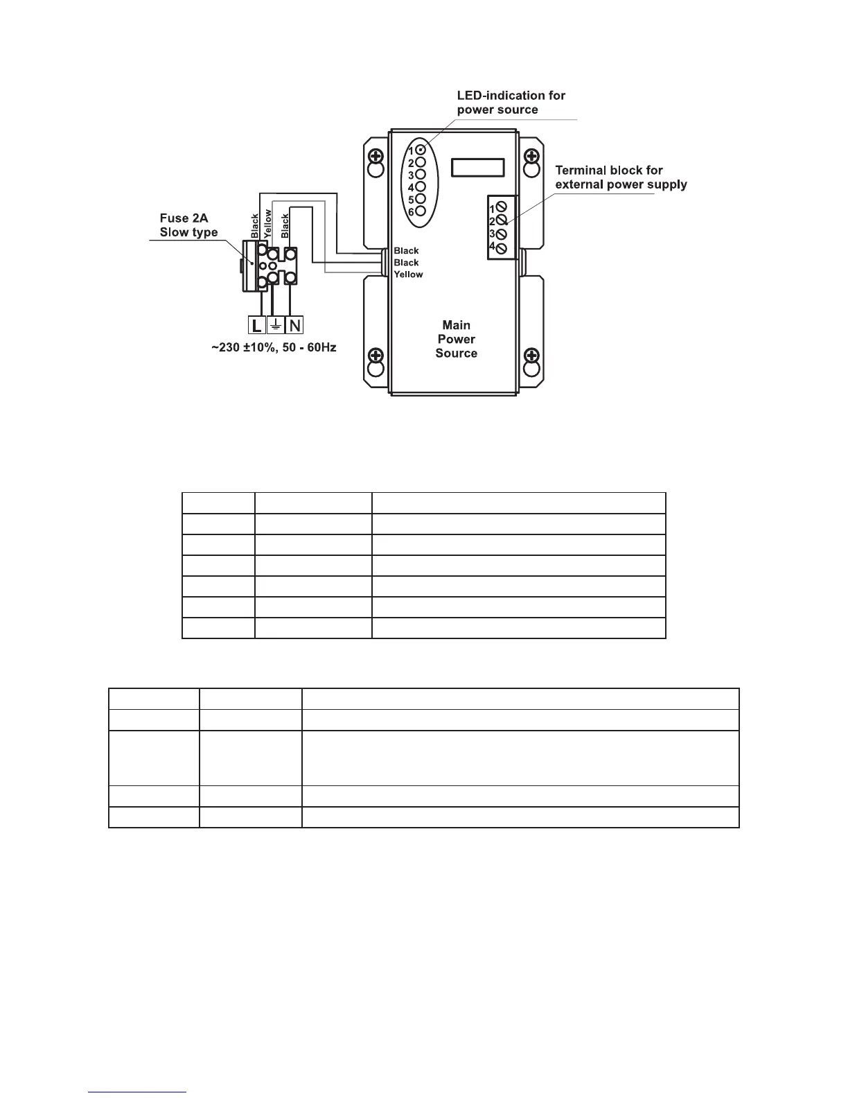
2.2.7 Main Power Source
Figure 19. General view of the power source and the terminal.
LED-indication of the power source
LED Function Description
1 AC LOSS Main power supply loss.
2 Charger Fault Problem with the battery charging.
3 BATT LOSS Battery loss.
4 BATT Low Discharged battery.
5 EARTH FAULT Earth connection ≤ 10kΩ.
6 Rx / Tx Shows the communication with the panel.
Terminal Block for connecting to external power supply.
Terminal Function Description
1 GND Input for connectin of external power supply EARTH.
2 FAULT OUT Fault output, turns on when a problem with the main power supply
occurred. Connect it to the input (Fault In) of the external power
supply.
3 FAULT IN Input for connecting the Fault output of the external power supply.
4 +13.8V External power supply input.
!
Before the mains supply is switched on, check the correct connection of each loop, sounder
or any other input or output.