Fire Panel IRIS - Installation Manual 19
3.2.1.1 Physical Address of Periphery Device
The panel is able to operate with up to 5 periphery devices, addressed 1 to 5. The devices can be self-ad-
dressed, whereby the first along the link acquires the lowest address. The power supply always acquires
address 1.
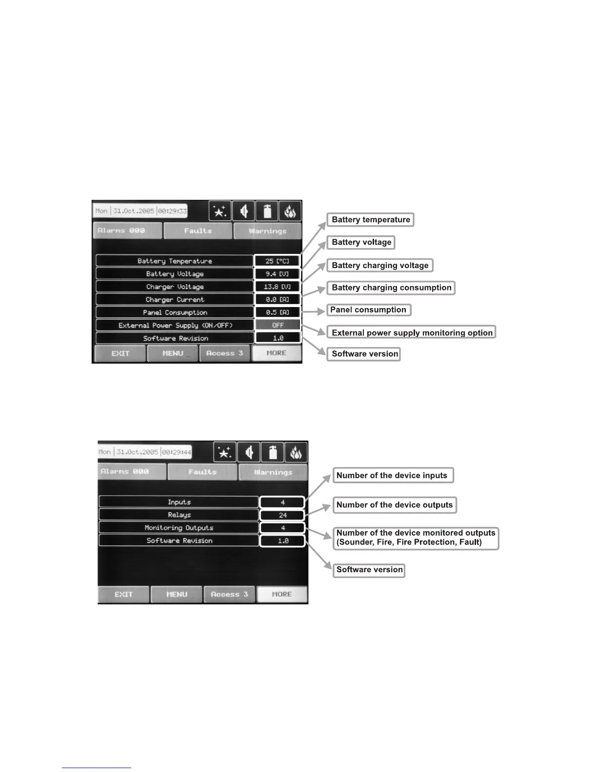
3.1.1.2 Button for Entering the Device Submenu
There is a menu for each periphery device which displays its current configuration and parameters. On Fig.
Screen 5 is shown the submenu of the first periphery device in the panel configuration (Power source PSU),
where it is possible to follow the current information for the main and additional power supply. On Fig. Screen
6 is shown the submenu of the second device in the system configuration (Main board – I/O4, or Main board +
20 Relay Expander – I/O24), and on Fig. Screen 7 – the third available periphery device (First Loop expander
– LOOP1).
Fig. Screen 5 – PSU (Power source)
Fig. Screen 6 – I/O24 (Main board + 20 Relay Expander Module)