Fire Panel IRIS - Installation Manual 9
2.2.3 Main Board
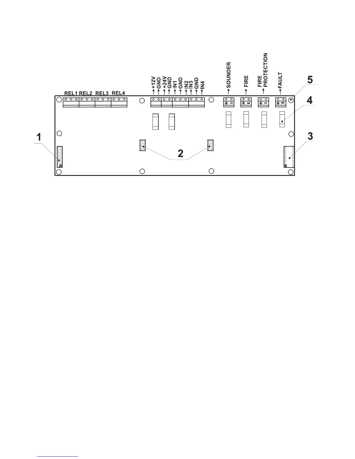
The Main Board (Figure 11) is a basic part of the fire panel IRIS. Its function is to control the output devices
– sounders, fire detectors, signaling devices, etc. The Main Board could not work independently.
Figure 11 – General view of the Main Board of the fire panel.
· REL1, REL2, REL3 and REL4 – Programmable outputs, 230V / 10A;
·
+24V and +12V – DC power supply terminals;
·
GND – Common earth
·
IN1, IN2, IN3 and IN4 – Inputs (Each input is independent from the others);
· SOUNDER – Monitored output for connecting of a sounder, 24 VDC / 0,5 A;
· FIRE, FIRE PROTECTION and FAULT – Monitored outputs for connecting of different
devices (e.g. signaling devices), 24V / 0,5A;
1 - Flat-cable interface connector for front panel power supply;
2 - Flat-cable interface connectors for connecting 20 Relay Expander Module;
(At connecting 20 Relay Expander Module to the system configuration, the total number of
the programmable outputs increases to 24.)
3 - Flat-cable interface connector for connecting 20 Relay Expander Module;
4 - Fuse 0,5A, type Self-recovering;
5 - Mounting holes.