8 Fire Panel IRIS - Installation Manual
2.2 System components
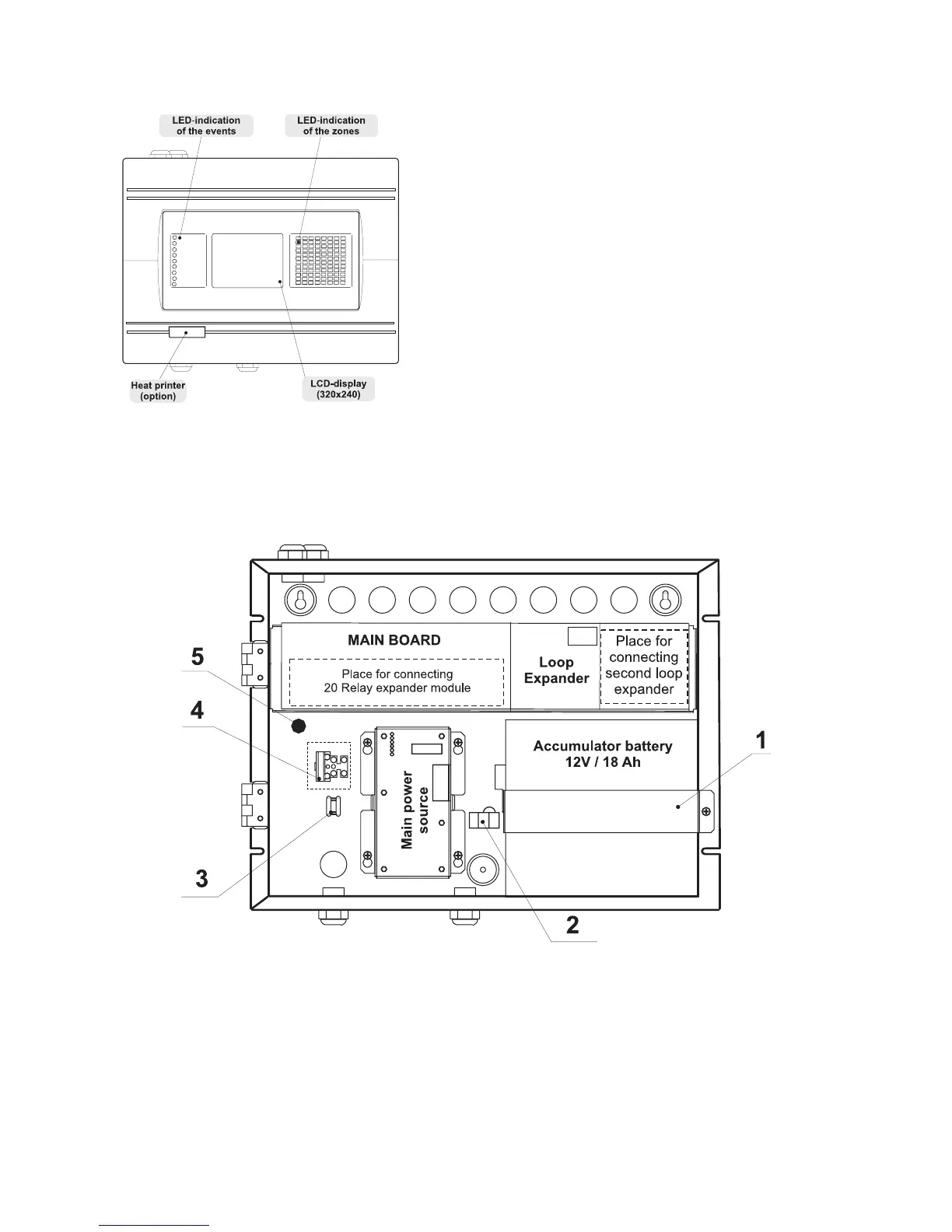
2.2.1 Front panel
Figure 9.
Main view of the front panel.
2.2.2 Configuration of the basic modules
Figure 10. Configuration of the basic modules in the system.
1 - Metal Clamp for supporting the accumulator battery.
2 - Terminal for connection between the accumulator battery and the main power source.
An automobile type fuse 10A is situated into the terminal.
3 - Clamp for supporting the main power supply cable.
4 - Terminal for connection between the mains power supply and the power source.
A slow type fuse 12A is situated into the terminal.
5 - Earthing lead.
LED-indication of the events provides following
functions:
1 - GENERAL FIRE
2 - PREALARM
3 - GENERAL FAULT
4 - SYSTEM FAULT
5 - SYSTEM SILENCE
6 - DELAY
7 - DISABLE
8 - TEST
9 - POWER ON