7
2 Connecting the terminals and putting into operation
Attention! Do NOT connect the metallic parts of the GSM antenna connector or the
terminals of the device directly or indirectly to the protective ground, because this may
damage the device!
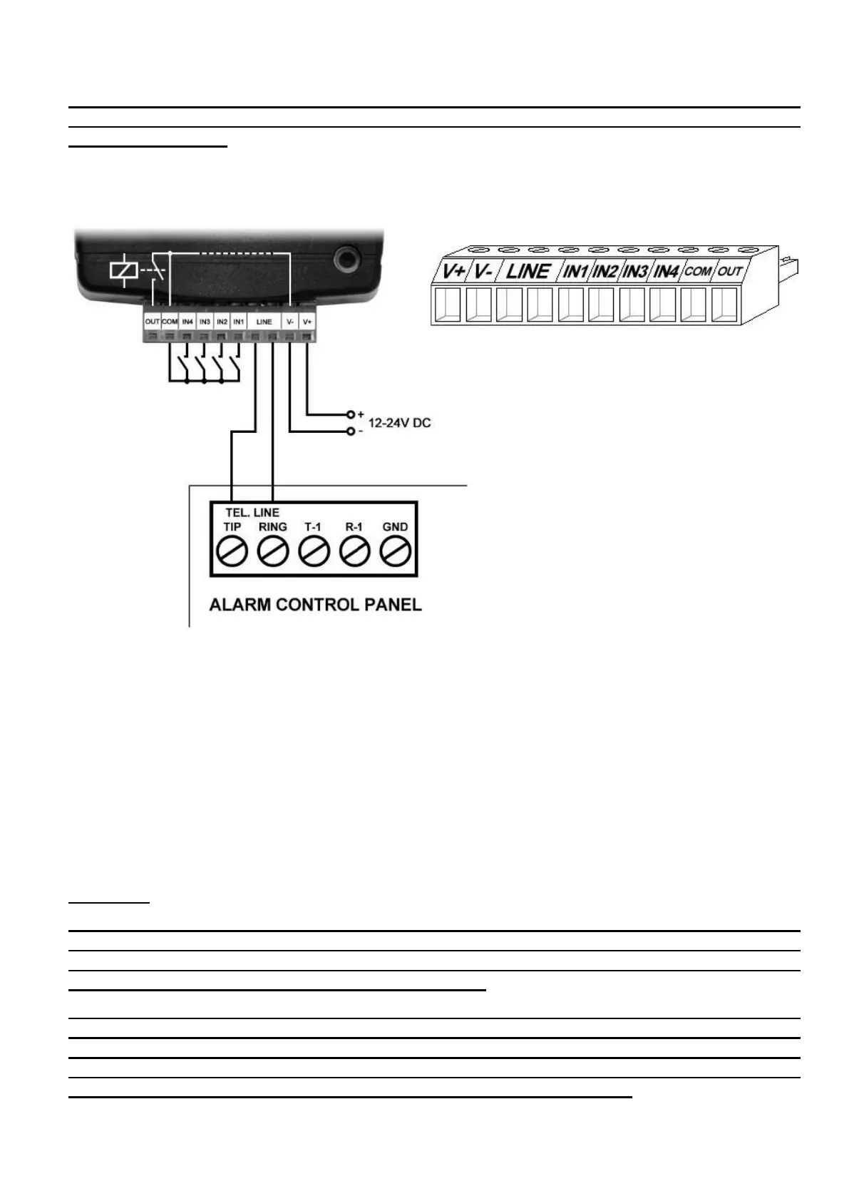
2.1 Connections and wiring
System terminal inputs and outputs:
V+ Supply voltage 12…24V DC (min. 500mA)
V- Supply voltage negative
LINE Simulated phone line output (connect to alarm system phone line input terminals)
IN1 Dry contact input 1
IN2 Dry contact input 2
IN3 Dry contact input 3
IN4 Dry contact input 4
COM Common negative for the contact inputs and the output (potential equivalent with V-)
OUT Relay output (switches the negative, max. 1A)
Attention!
Although the COM and V- terminals are equivalent, due to the design of internal circuit
protections, the COM terminal shall not be used as negative input for powering the device,
because this may damage the device! The COM terminal should only be used for
connecting the contact inputs and the relay output!
We would not advise powering the device directly from the power output of the alarm
control panel (AUX), as we can’t guarantee that the given output is able to fully operate the
device. Insufficient powering may lead to communication errors and frequent device
restarting, making it impossible for the device to operate normally as expected. To avoid
this, we suggest that you use a separate power supply for the device.