Aligna
®
4D User Manual
23 / 84
4.4.3.4 Short Distance Wedge Plate
If there is not enough space for this distance (especially, if the
beam diameter is large), the wedge plate can be oriented vice versa,
so the part beam from the front and from the back surface combine
approximately the position detector chip. Of course, there will ap-
pear interference fringes at the detector chip. However due to the
well-selected wedge angle these fringes are so narrow, that they
wipe out by integration over very many fringes.
(In this case, the wedge angle has to be selected rather carefully:
The focused spots at the angle detector chip have to be separated
distinctly more than the A chip size, while both un-focused spots at
the B chip should fit completely to the chip size.)
If the 2 x 0.9% reflectivity is too high (the 2% of power should not be
lost, or the sampled beam becomes very strong because of high laser
power) the sampler plate can be oriented at Brewster's Angle (about
57°) instead of 45°.
Because of the smaller angle, the demands on the surface quality of the sampler plate are
higher, and the size of the plate must be larger, compared to 45°. In addition, the sampled
beam comes out at a less convenient angle (compared to 90° with 45° plates).
4.4.4 AR-Coated Windows at
Small Angle
The wedge plates (or un-wedged plates with ultra-
fast lasers) at 45° or larger angle have two draw-
backs:
1. The sampling is strongly dependent on the polari-
zation (p-light necessary!), and the out-coupling
might be too strong for high power lasers.
2. AR coatings at 45° are difficult to get from stock
and have much less assortment at most optics
suppliers.
Custom-made AR coated wedge plates (at 45°) are a solution. They can reduce the reflectivity
of the s-light from 12% down to 0.3% and of the p-light down to 0.1 % or so. However, they are
difficult to get from stock. Thus, they have to be specially coated, and therefore are rather
expensive and have a long lead-time.
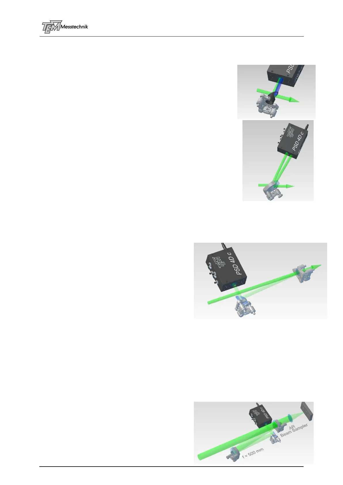
Using commercially available AR coated windows (with or without wedge angle) are a practical
solution. They can be (and have to be) operated close to 0° angle of incidence (AOI). Typically
<12° is within the specs range of the coatings. An additional folding mirror helps avoiding too
long distance from the sampler to the detector, and allows for a convenient sample beam
alignment.
Due to the small AOI the polarization dependence is
negligible, so this setup also works fine for un-
polarized or randomly polarized lasers (for example
some fiber lasers, or lasers which have been guided
through a non-polarization-maintaining fiber, or