1-22
System Overview
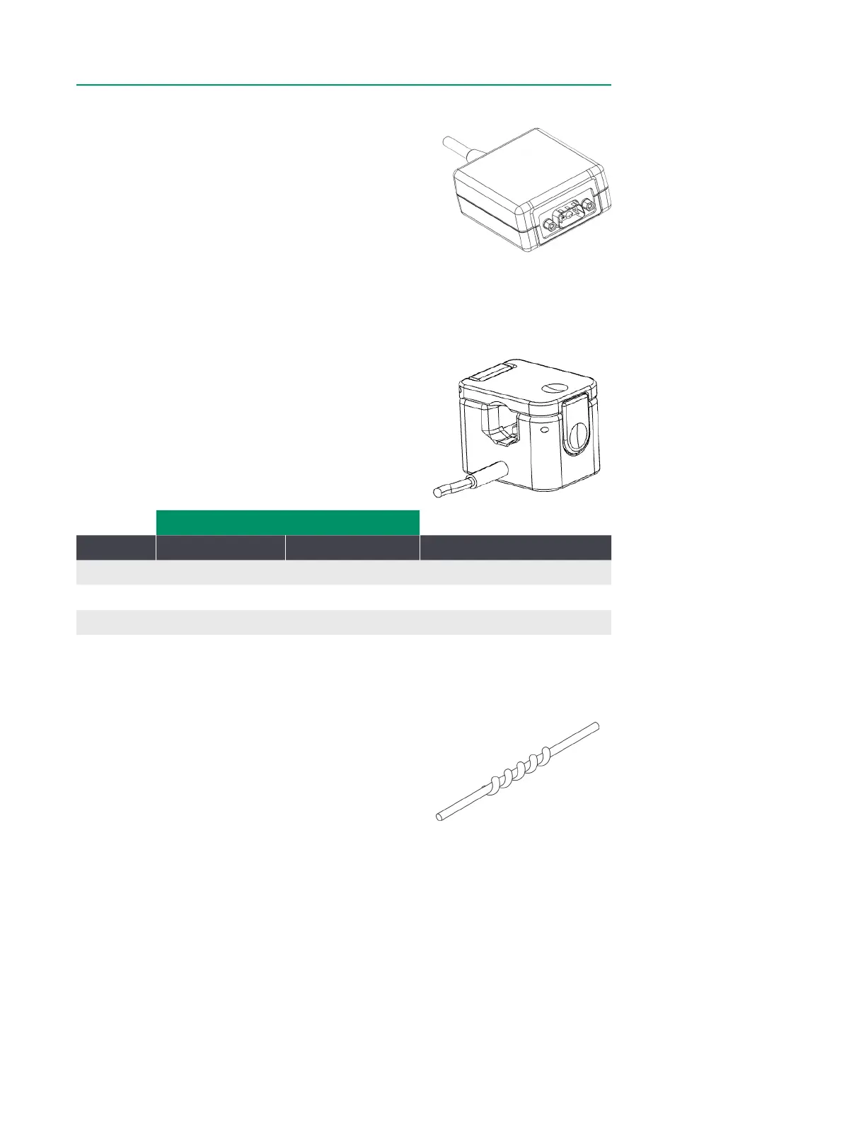
Flow Interface ModuleFlow Interface Module
The CDI OneView Flow Interface Module connects Flow
Sensors to the Core. The Flow Module contains memory
to store sensor identication and conguration
information.
Flow Sensors Flow Sensors
The CDI OneView Flow Sensor measures blood ow circulating in the perfusion circuit.
Multiple sensor sizes are available for use with a wide variety of tubing types and
sizes. The system allows connection and conguration of up to four ow sensors.
The source of blood ow rate used in calculations can be customized through system
conguration.
The sensors use a clamp-on mechanism to t around
different sizes of exible tubing of the extracorporeal
circuit. Sensors are labeled to indicate direction of ow
to facilitate correct installation. Each sensor ts around
a specic size of tubing and is suitable for a specic
range of ows as indicated in the table below:
Compatible with PVC tubing:Compatible with PVC tubing:
Sensor Inner diameter Wall thickness Flow rate range (mL/min)
1 3/8” 3/32” 200 – 8,000
2 1/4” 3/32” 50 – 2,500
3 1/4” 1/16” 50 – 2,500
Flow Sensor IdentifiersFlow Sensor Identifiers
Flow Sensor identiers are included within the packaging
of each sensor. These color-coded identiers can be
wrapped around a Flow Sensor cable to associate the
sensor with its corresponding readout on the Display.