3-6
Case Profile Configuration
Sensor ConnectionsSensor Connections
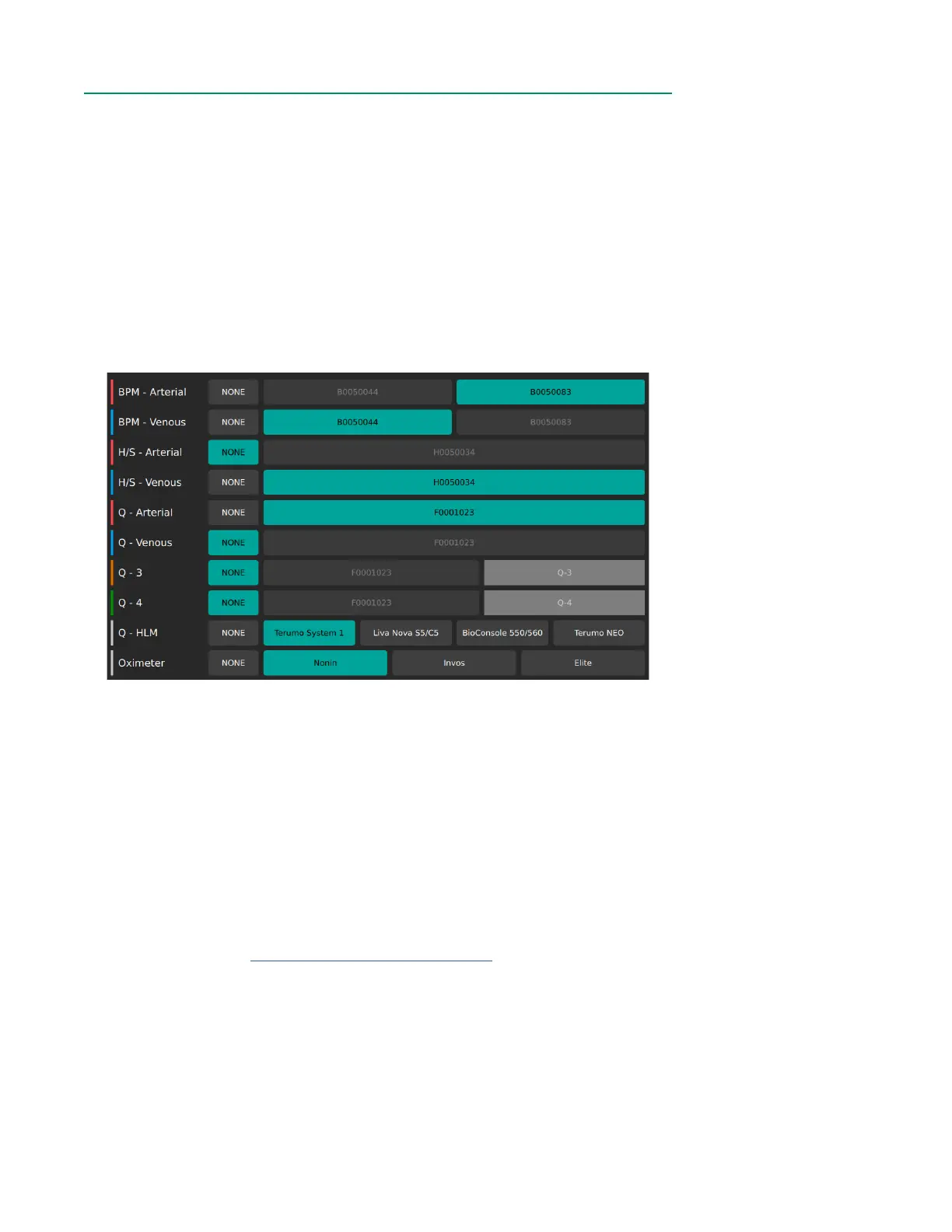
The Sensor Connections Tab shows the modules currently connected to the Core and
allows the user to congure what modules will be visible during measurement. Use the
scrollbar on the right to navigate through all connections.
Module types are listed in the following order:
• Arterial and Venous BPMs
• Arterial and Venous H/Ss
• Flow Sensors
• HLM
• Oximeter
Once a module connection is made to the Core, the serial number will appear on the
screen next to the appropriate category. There is no default setting for connected
modules. When a module is not connected, it defaults to NONE.
To show the blood parameters from a sensor in Measurement Mode, assign its
corresponding serial number to a sensor type (Arterial, Venous, etc.). If a BPM or H/S
Probe is assigned as arterial, its LED indicator light will illuminate red. If a BPM or H/S
Probe is assigned as venous, its LED indicator light will illuminate blue.
The names for the rst two Flow Sensors default to Q - Arterial for red and Q - Venous
for blue. The orange and green Flow Sensors can be given custom names of up to
ve characters by tapping the corresponding category after choosing a serial number.
The color for each Flow Sensor category should match the color indicator placed on
the physical sensor (see Chapter 1, “Flow Sensor Identiers”).
For the HLM and Oximeter categories, tap the corresponding device name. Only one
selection is allowed for each of these modules.
If a serial number button is greyed out, then that module has already been assigned.
If a selection is highlighted in green, then the associated parameter will be available in
the Display Layout Builder. If NONE is highlighted in green, then that parameter will not
be available in the Display Layout Builder.