5-13
Running a Case
ScreenshotScreenshot
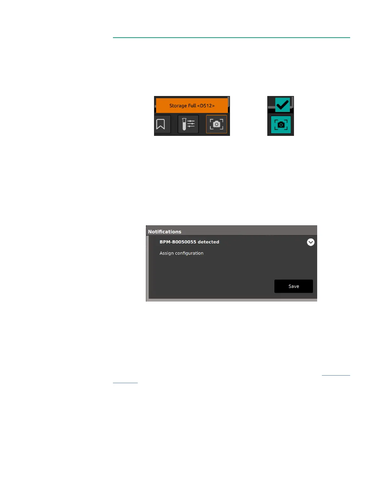
Tap the Screenshot button to capture and save a copy of the currently displayed screen.
• If a screenshot capture fails, a pop-up message will show Screenshot failed.
• A checkmark highlighted in green appears if a screenshot capture is successful.
All screenshots can be downloaded to a USB drive through the Data Export Tab.
Module ReplacementModule Replacement
A BPM, H/S Probe or module can be replaced during a case.
1. Unplug the corresponding probe or module from the Core.
2. Plug in the replacement probe or module.
3. Conrm successful connection using the Message Center.
Note: A replacement H/S Probe will need to be docked on the H/S Probe
holder to perform its color chip test.
Note: It will take the system time to detect and perform diagnostics for the
newly connected probe or module.
4. Once detected, the system will resume measurement for associated parameters.
Touchscreen DeactivationTouchscreen Deactivation
The touchscreen can be disabled to allow for cleaning or repositioning. See Chapter 1,
“Display” for the location of the touchscreen deactivation button.
• To disable the touchscreen, press and hold the touchscreen deactivation button
for one second. This button is to the left of the system power button at the bottom
of the Display.
• While the touchscreen is inactive, the Display will remain on, but all touchscreen
features will be disabled. An orange border is shown on screen during this time.
• To reactivate the touchscreen, press the same button until the orange border is
removed.
Screenshot failed Screenshot successful