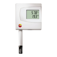
4 Transmitter
21
1. Create a wall opening (approx. 120 mm x 220 mm) at the
mounting location.
2. Hold 6383 in assembly position and mark the drill holes.
3. Drill holes suitable for the screws to be used.
4. Connect 6383.
4.3.2. Connecting the instrument
Electrical voltage
Danger of injury!
> De-energize the mains connection before connecting the
transmitter.
Only have the transmitter wired and connected by
authorized personnel with the voltage disconnected.
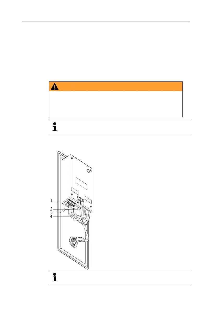
4.3.2.1. Overview of terminals
1 Terminal strip for voltage
supply and analog outputs
2 Relay terminal strip (option),
below the relay cover
3 Relay cover (option)
4 Insulating trough for relay
board (option), below the
relay cover
The following description of the terminals refer to this
overview and its numbering.