4 Transmitter
22
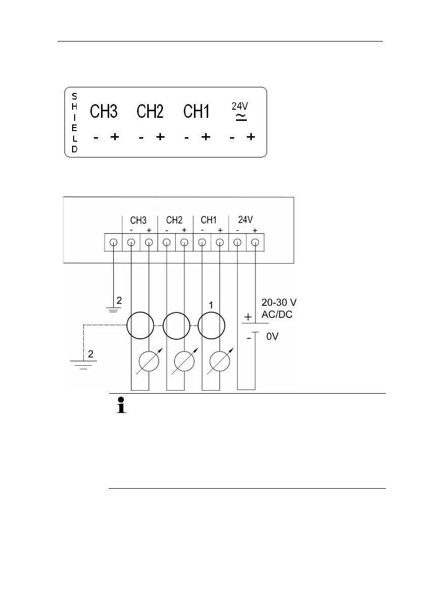
4.3.2.2. Connecting voltage supply and analog outputs
Terminal strip for voltage
supply and analog outputs,
item (1) of overview of
terminals
Wiring diagram for 4-wire system (0 to 20 mA/4 to 20 mA/0 to 1
V/0 to 5 V/0 to 10 V)
1 1 or 3 channels,
0 to 20 mA/4 to
20 mA max.
load per 500 Ω
0 to 1 V / 0 to
5 V / 0 to 10 V
2 Functional earth
Requirement for the connecting cable of the supply:
• Shielded and insulated with cross-section of at least
0.25 sq. mm, maximum 1.5 sq. mm without wire end
sleeves.
• The supply line must be secured against exceeding
0.5 A.
• An OFF switch must be installed in an easily accessible
position close by and be marked as such.
1. Disconnect terminal strip for voltage supply and analog outputs.
2. Strip the cable ends, clamp wire end ferrules on and screw
down with voltage terminals/channel terminals.