6 Commissioning
46
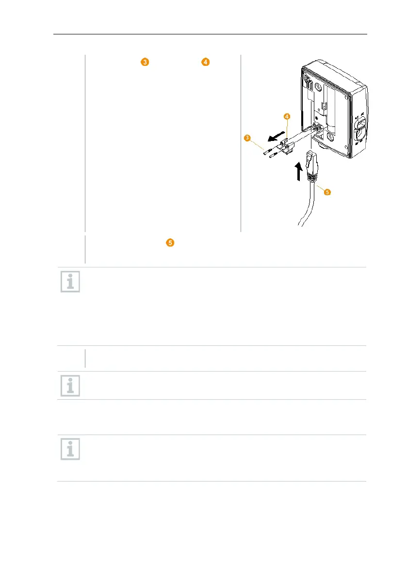
Undo screws on the panel for the
network cable and remove panel.
Slide network cable with the tongue pointing up into the Ethernet port
until it clicks into place.
If you wish to connect the Saveris Ethernet data logger to the power
supply via the 24 V AC/DC plug-
in/screw terminal and not via the mains
adapter, do not screw on the housing cover until after connecting the
power supply.
The procedure for connecting the power supply via the plug-in/screw
terminal is the same as for the Saveris router; see section 6.9.5.1
Connecting testo Saveris router to power supply (mains unit).
Place the housing cover on the data logger and screw it down.
You can integrate the data logger into the network via a network switch.
6.9.2.2 Connecting testo Saveris Ethernet data logger to
power supply (mains unit)
The procedure for connecting the power supply via the 24 V AC/DC
plug-in/screw terminal is the same as for the Saveris router; see secti
6.9.5.1 Connecting testo Saveris router to power supply (mains
unit).