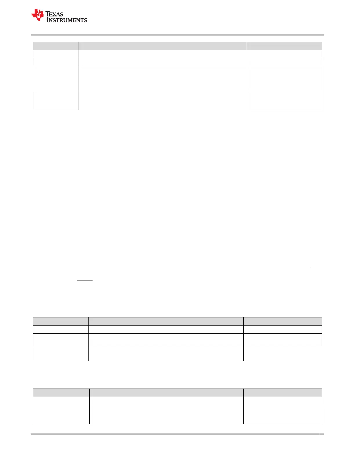
Status Condition Action
Normal Current() > OCD:Threshold SafetyAlert()[OCD] = 0
Alert Current() ≤ OCD:Threshold SafetyAlert()[OCD] = 1
Trip Current() continuous ≤ OCD:Threshold for OCD:Delay duration
SafetyAlert()[OCD1] = 0
SafetyStatus()[OCD] = 1
BatteryStatus()[TDA] = 0
OperationStatus()[XDSG] = 1
Recovery
[SafetyStatus()[OCD] = 1 AND
Current() continuous ≥ OCD:Recovery Threshold for OCD:Recovery Delay
time
SafetyStatus()[OCD] = 0
BatteryStatus()[TDA] = 0
OperationStatus()[XDSG] = 0
2.6 Hardware-Based Protection
The BQ28Z610-R2 device has three main hardware-based protections—AOLD, ASCC, and ASCD1,2—with
adjustable current and delay time. Setting AFE Protection Configuration[RSNS] divides the threshold value
in half. The Threshold settings are in mV; therefore, the actual current that triggers the protection is based on
the R
SENSE
used in the schematic design (see the BQ28Z610-R1 1-Cell to 2-Series Cell Li-Ion Battery Pack
Manager Data Sheet).
In addition, setting the AFE Protection Configuration[SCDDx2] bit provides an option to double all of the
SCD1,2 delay times for maximum flexibility towards the application's needs.
For details on how to configure the AFE hardware protection, refer to the tables in AFE Threshold and Delay
Settings.
All of the hardware-based protections provide a short term Trip/Recovery protection to account for a current
spike. The fault protection detects current spikes and after a delay time will turn OFF both FETs. Then with a
delay up to 250 ms, the non-appropriate FET associated with the fault condition will turn back ON. The recovery
method is a timer-based recovery set in Protections.
Generally, when a fault is detected after the Delay time, both CHG and DSG FETs will be disabled (Trip stage).
Since both FETs are off, the current will drop to 0 mA. After Recovery time, the CHG FET or DSG FET will be
turned on again (Recovery stage) based on the fault condition.
The Trip/Recovery are documented in each of the following hardware-based protection sections.
Note
There is no PRES pin on the BQ28Z610-R2 device.
2.6.1 Overload in Discharge Protection
The device has a hardware-based overload in discharge protection with adjustable current and delay.
Status Condition Action
Normal Current() > (AOLD Threshold[3:0]/R
SENSE
) SafetyAlert()[AOLD] = 0
Trip
Current() continuous ≤ (AOLD Threshold[3:0]/R
SENSE
) for AOLD
Threshold[7:4] duration
SafetyStatus()[AOLD] = 1
OperationStatus()[XDSG] = 1
Recovery SafetyStatus()[AOLD] = 1 for OLD:Recovery time
SafetyStatus()[AOLD] = 0
OperationStatus()[XDSG] = 0
2.6.2 Short Circuit in Charge Protection
The device has a hardware-based short circuit in charge protection with adjustable current and delay.
Status Condition Action
Normal Current() > (ASCC Threshold[2:0]/R
SENSE
) SafetyAlert()[ASCC] = 0
Trip
Current() continuous ≤ (ASCC Threshold[2:0]/R
SENSE
) for ASCC
Threshold[7:4] duration
SafetyStatus()[ASCC] = 1
BatteryStatus()[TCA] = 1
OperationStatus()[XCHG] = 1
www.ti.com Protections
SLUUCO0 – APRIL 2022
Submit Document Feedback
BQ28Z610-R2 15
Copyright © 2022 Texas Instruments Incorporated

 Loading...


