© 2011 Thorlabs
117Operating the Beam Profiler
3.5.6.7
Troubleshooting
Some typical problems which might occur are discussed in the following.
The beam does not hit the CCD sensor of the camera for all stage positions.
Aligning the beam is necessary, see section Beam Alignment .
A timeout occurs during a measurement.
A timeout always occurs when the Beam Profiler camera does not get a valid image.
This may happen
if the camera is saturated. Since the beam is focussed the intensity
increases for small beam widths. This may lead to a saturation of the
camera. Attenuate the laser beam with additional ND filters or decrease the
laser output power. Alternatively increase the focal length (which increases
the spot size of the beam) when possible.
if Normal Scan is applied and the Fine Scan shall add data points then the
exposure time has to change from long exposure times to small ones. This
can take more time than the timeout allows. Set the timeout to a greater
value to solve this problem (M² Settings ).
if the beam power is too low. Remove ND filters or increase output power of
the laser.
if the beam size is too small and no ellipse could be calculated (if Clip
Level Ellipse is selected as beam width). Use a longer focal length to avoid
beam size which are too small.
if the beam is outside the CCD chip. Align the beam, see section Beam
Alignment .
Parasitic reflections walk over the CCD sensor during the
measurement.
These reflections are due to the reflections of the laser light from the CCD to
a filter and back to the CCD sensor. This happens when the beam is not
perfectly aligned and/or the filters are not parallel to the CCD chip.
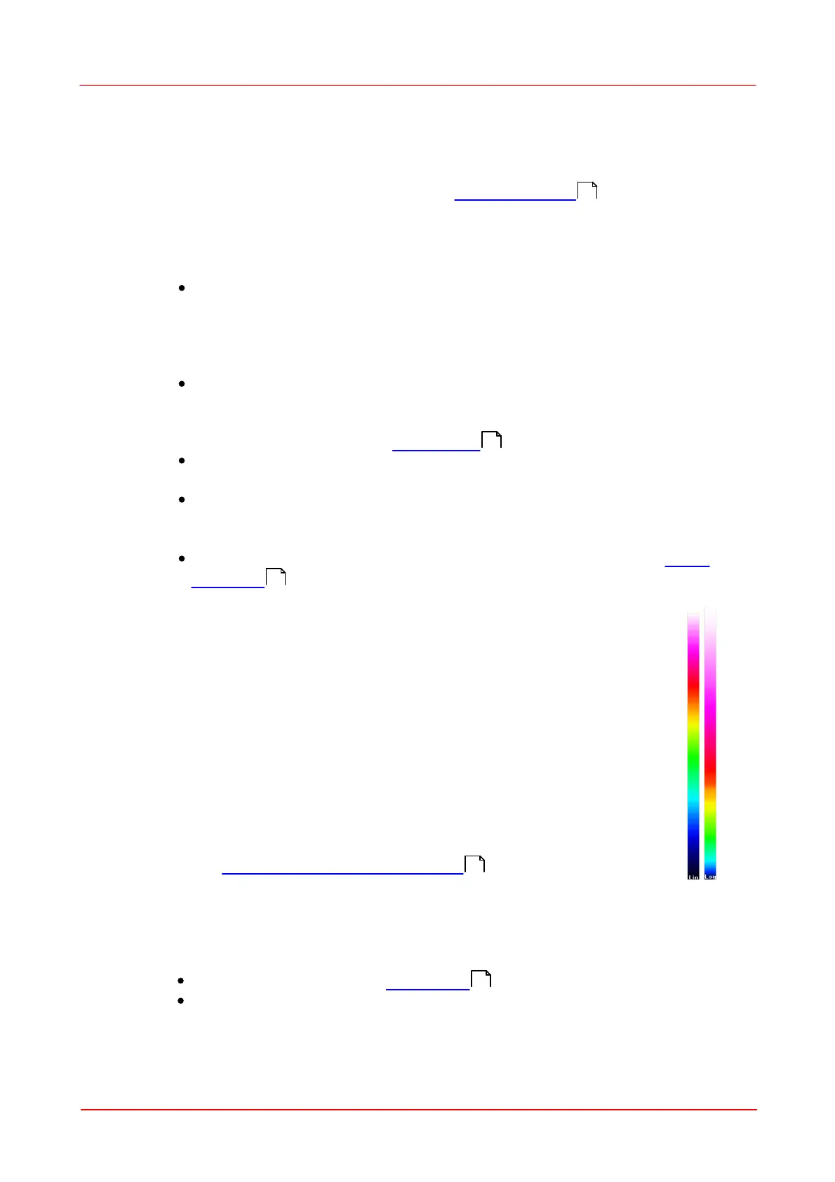
The detection of these reflections can be improved by using the logarithmic
color scale. A logarithmic scale pronounces smaller intensities which helps
to observe reflection with low intensities.
The scale can be switched from linear to logarithmic by clicking on the
color scale. An effective way to avoid these reflections is to use anti-
reflection coated ND filters.
See section M² Application recommendations to learn more about AR
coated filters and how to mount them.
The M² value differs extremely from the expected value.
For example, the beam has a nearly Gaussian intensity distribution and M² values
are larger than 1.1:
check set wavelength (see M² Settings )
check Clip Level of the Calculation Area.
If the selected Clip Level is too high, the beam might be cut and will be
measured too small. This results in a too small beam waist and a too small
100
107
100
85
107
 Loading...