8
Chapter 2 Basic Specifications
2.1 Measurement Functions
2.1.1 Measurement Parameters
L: Inductance
C: Capacitance
R: Resistance
|Z|: Absolute value of impedance
X: Reactance
B: Susceptance
G: Conductance
D: Dissipation factor
θ: Phase angle
Q: Quality factor
2.1.2 Combinations of Measurement Parameters
Suffix “s” means series; suffix “p” means parallel.
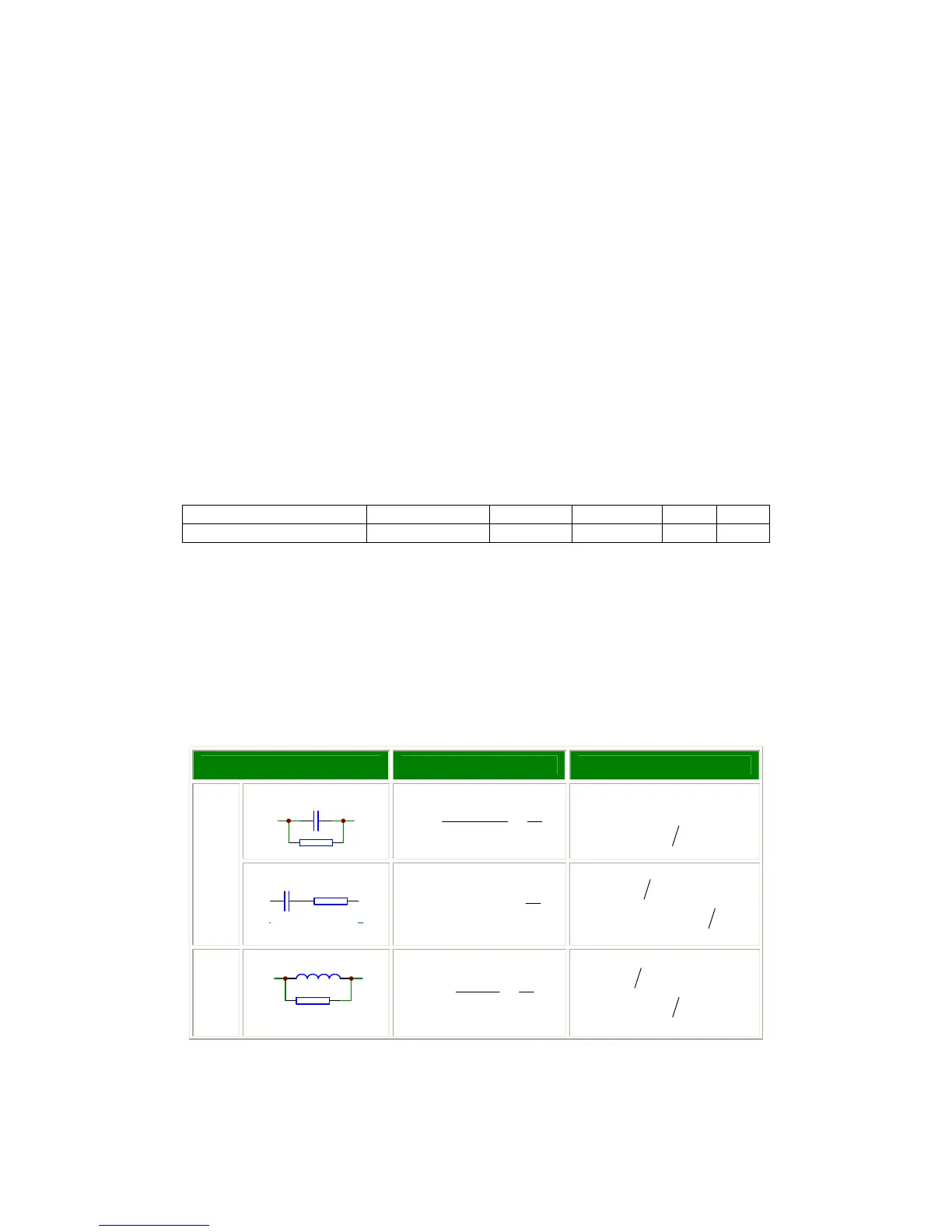
2.1.3 Equivalent Circuit
The actual capacitor, resistor and inductor are not the ideal capacitor, resistor and
inductor. Normally, a component has the characteristics of the resistor and the
reactor at the same time. The actual component is composed of an ideal resistor and
reactor (ideal inductor or capacitor) in series or parallel equivalent circuits.
The values in the two different equivalent circuits can be converted to each other
using the following formulas in Table 2-1. The values are different due to the quality
factor Q (or the dissipation factor D).
Table 2-1 Parallel and Series Circuit Mode
Circuit Mode Dissipation Factor Conversion
Cp
QRfC
D
Pp
1
2
1
==
π
)1(
)1(
22
2
DDRR
CDC
PS
PS
+=
+=
C
Cs
Rs
Q
CfRD
SS
1
2 ==
π
22
2
)1(
)1(1
DDRR
CDC
SP
SP
+=
+=
L
Lp
Rp
QR
fL
D
P
P
1
2
==
π
)1(
)1(1
22
2
DDRR
LDL
PS
PS
+=
+=
Main parameters Z L C R G
Secondary parameters θ(deg), θ(rad) Q,R
s
,R