EXV2
/TRIG
COM2
接口连接器
HANDLER
14,15
12,13
32,33
触发限流电阻
内部
+5V
电源
*
*
2.2k
J904
仪器参考地
*
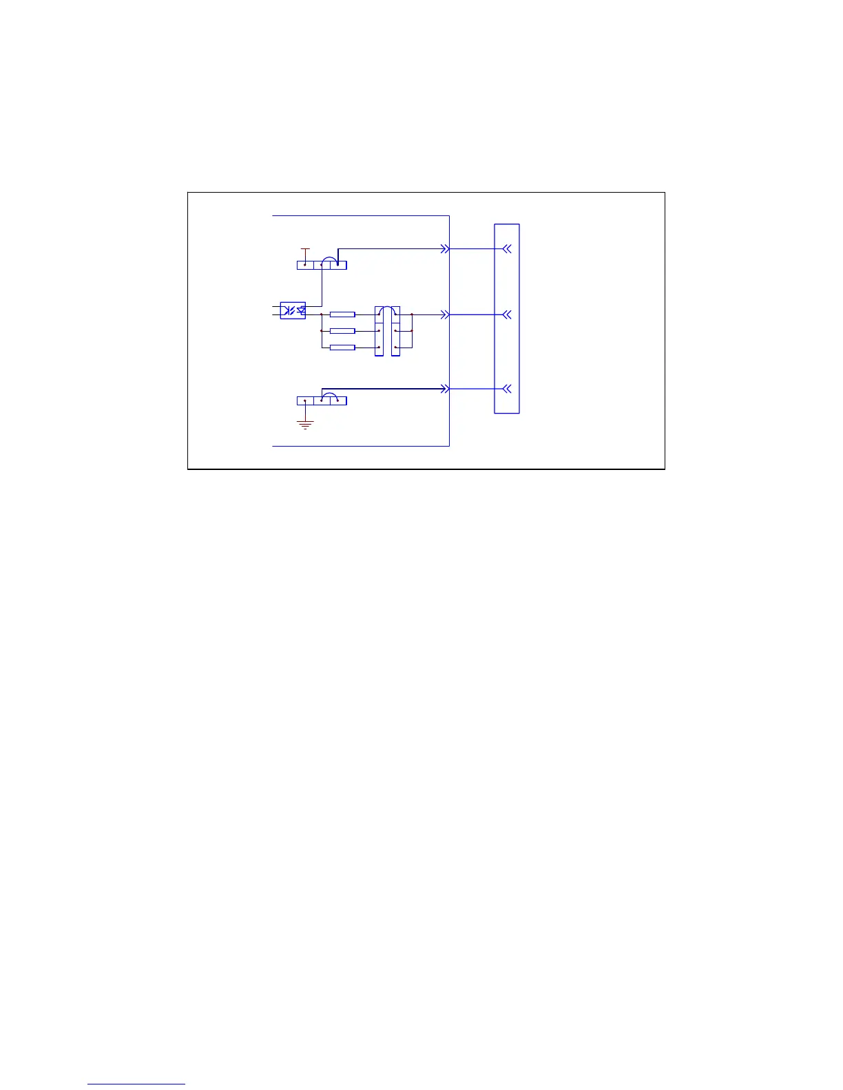
7.3.2 DC Isolated Input
The /TRIG signal (pin 12 and 13) is connected to the cathode of the LED in an
opto-coupler. TH2816B is triggered on the rising edge of the /TRIG pulse. The anode
of the LED can be powered from the internal 5 V, or by an external voltage source
EXTV2.
*为出厂时默认的跳线位置
Figure 7-8 Handler Interface Input Signal Diagram
T
o limit the trigger current, jumper J905 must be selected considering the optocoupler
anode voltage being used.
7.4 Setting Up the Handler Interface Board
Jumpers on the Handler Interface board must be set to select the signal outputs
(Open collector, internal voltage outputs, or External voltage outputs). A description of
each jumper is given in Table 7-5, and their locations are shown in Figure 7-9.
When shipped from the factory, each jumper is set to the (N) position (marked “N” on
the handler interface board).
Jumper J901 and J902 are used to select the internal voltage or external voltage for
the output signals.
Jumper J903 and J904 are used to select the internal voltage or external voltage for
the control signals.
Jumper J905 is used to select the current limiting resistor under different voltage
range.