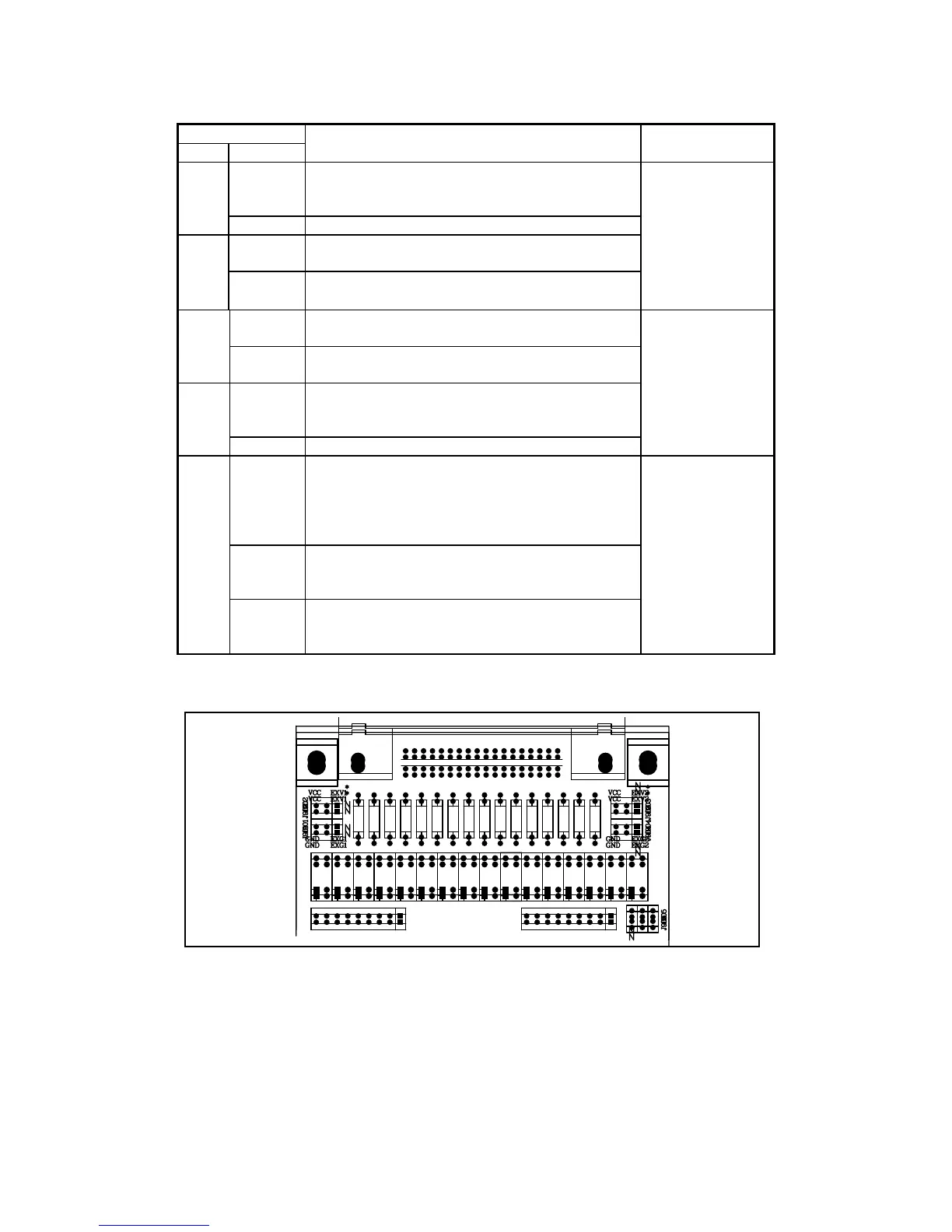
90
Jumper
No. Position
Description Signals
Left
DC isolated outputs are not isolated.
COM1 is connected to TH2816B circuit
common.
J901
Right(N) DC isolated outputs are isolated.
Left
The open collector outputs are pulled up to the
internal VCC (+5 V).
J902
Right(N)
The open collector outputs are pulled up to the
external EXV1(+5V to +24V)。
/BIN1-/BIN3
/AUX
/OUT
/PHI
/PLO
/SREJ
Left
The open collector outputs are pulled up to the
internal VCC (+5V).
J903
Right(N)
The open collector outputs are pulled up to the
external EXV2 (+5V to +24V).
Left
DC isolated outputs are not isolated.
COM2 is connected to TH2816B circuit
common.
J904
Right(N) DC isolated outputs are isolated.
/IDX
/EOM
/TRIG
Left (N)
Trigger current limiting resistor is 680Ω.
This position should be set when EXV2 is
between 5V to 8V or when internal VCC is
used for control signals (J903 and J904 are set
to the left position).
Center
Trigger current limiting resistor is 1.2kΩ.
This position should be set when EXV2 is
between 8V to 15V.
J905
Right
Trigger current limiting resistor is 2.2kΩ.
This position should be set when EXV2 is
between 15V to 24V.
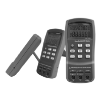
/TRIG
Figure 7-9. Handler Interface Input Signal Diagram