9
Lp Rp
QfL
R
D
S
S
1
2
==
π
22
2
)1(
)1(
DDRR
LDL
SP
SP
+=
+=
L: Inductor C: Capacitor f: Frequency
R: Resistor D: Dissipation factor Q: Quality factor
Suffix s: Series Suffix p: Parallel
The following description gives some practical guidelines for selecting the
capacitance measurement circuit mode.
a) We can select the circuit mode according to the variation of D at two different
frequencies. If the dissipation factor of a capacitor increases with the increase of
the test frequency, series circuit mode should be selected. If the dissipation factor
decreases with the increase of the test frequency, parallel circuit should be used.
For inductor, the situation is just in the opposite side. In fact, D is impossible in
direct ratio with the test frequency. From Figure 2-1, we can find that Rp and Rs
exist at the same time. If Rs is more significant than Rp, series mode is selected;
If Rp is more significant than Rs, parallel mode is more suitable.
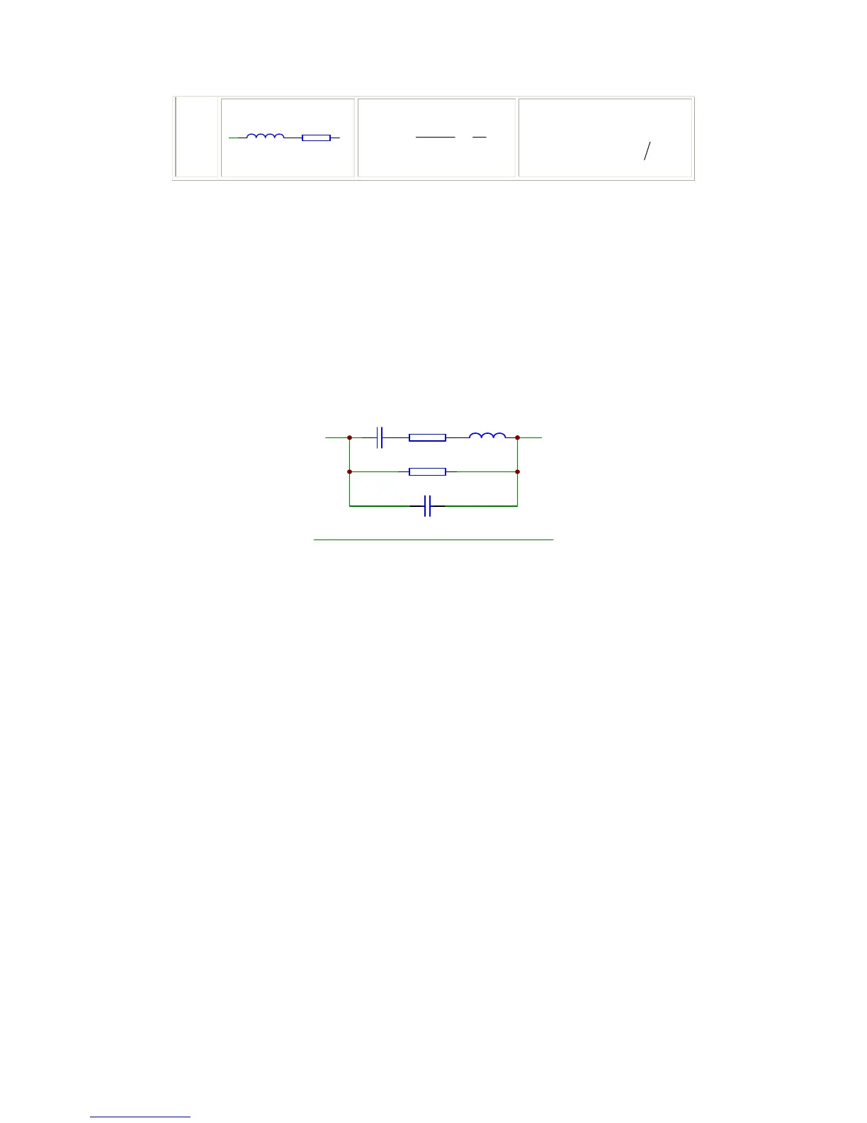
Cs
Rp
Cx
Rs Lo
Figure 2-1. Equivalent circuit of an actual capacitor
Where,
Cx: ideal capacitor
Rx: resistance of the leads
Lo: inductance of the leads
Rp: insulation resistance across the capacitor
Co: stray capacitor across the capacitor.
For a given frequency F, Cs and Cp can be calculated.
b) When there is no proper information available, please make decision according to
following rules:
For low impedance component(such as large capacitor or small inductor),
the series equivalent circuit mode should be used.
For high impedance component(such as small capacitor or large inductor),
the parallel equivalent circuit mode is the appropriate choice.
If a capacitor is used as a filter capacitor, series circuit mode is the best
choice.
If a capacitor is used in a LC oscillator then parallel circuit mode can be
selected.
2.1.4 Ranging
Auto and Manual (Hold/Up/Down), total 9 ranges.
2.1.5 Trigger
TH2816B has four trigger modes: INTernal, EXTernal, MANual, and BUS. Except for
BUS trigger mode these trigger modes can be set on the front panel. The BUS trigger
mode is used when TH2816B is controlled via GPIB.
Internal: When the trigger mode is set to INTernal trigger mode, TH2816B
continuously repeats measurements.