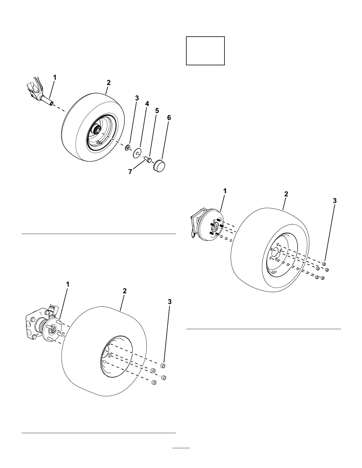
3. Install each tire as follows:
• 2-wheel-drive machines:
A. Apply thread-locking compound to the
bolt (5/8 x 1-1/4 inch).
B. Use a small washer , large washer , bolt
(5/8 x 1-1/4 inch), and to secure the
wheel to the axle spindle ( Figure 3 ).
g312833
Figure 3
1. Axle spindle
5. Bolt (5/8 x 1-1/4 inch)
2. T ire 6. Dust cap
3. Small washer
7. Apply thread-locking
compound to the bolt.
4. Large washer
C. T orque the bolt to 203 N∙m (150 ft-lb).
D. Install the dust cap to the wheel ( Figure
3 ).
• 4-wheel-drive machines: Use 4 lug nuts to
secure the wheel to the wheel hub ( Figure 4 ).
g299549
Figure 4
1. Wheel hub 3. Lug nut
2. T ire
4. T orque the wheel lug nuts; refer to T orquing the
Wheel-Lug Nuts ( page 62 ) .
3
Removing the Front T ires
Models 31900A, 31901A, and
31907A Only
No Parts Required
Procedure
Note: Y ou must perform this procedure to correctly
install the lift arms.
1. Loosen and remove the wheel lug nuts ( Figure
1 1 ).
g299550
Figure 5
1. Wheel hub 3. Lug nut
2. T ire
2. Removed the wheels from the wheel hubs
( Figure 1 1 ).
13