g312025
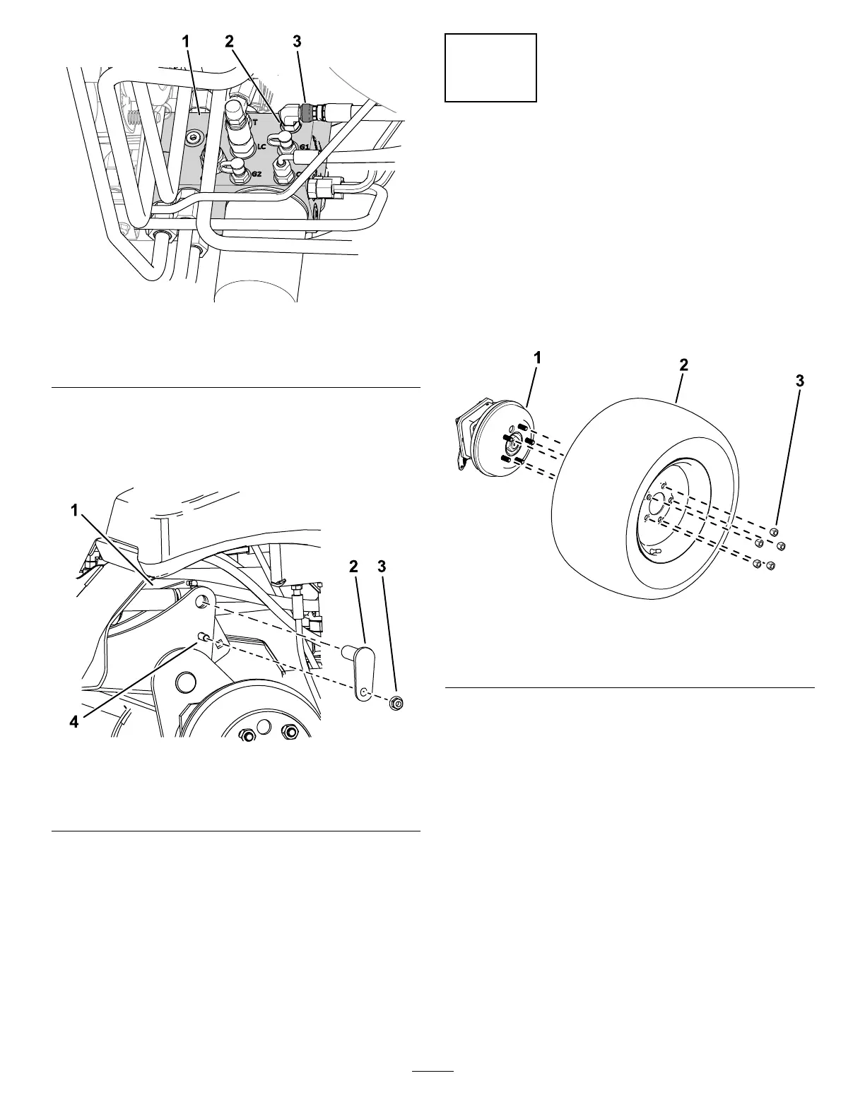
Figure 9
1. Manifold
3. Hose swivel nut
2. Port C1
C. Use a drift punch to align the cylinder rod
holes with the lift-arm holes ( Figure 10 ).
Note: Fully raise the lift arm to help with
the alignment.
g467781
Figure 10
1. Cylinder rod 3. Nut (3/8 inch)
2. Small pin 4. Bolt (3/8 x 1-1/4 inches)
D. Use 2 bolts (3/8 x 1-1/4 inches), 2 nuts (3/8
inch), and 2 small pins to secure the lift
arms to the cylinders ( Figure 10 ).
E. T orque the hose swivel nut on port C1 to
41 N∙m (30 ft-lb).
Note: Use a backup wrench to prevent the
hose from twisting.
6. Grease the attachment pin joints and lift-arm
pin joints; refer to Greasing the Bearings and
Bushings ( page 51 ) .
5
Installing the Front T ires
Models 31900A, 31901A, and
31907A Only
No Parts Required
Procedure
1. Use the previously-removed lug nuts to secure
the tires to the wheel hubs ( Figure 1 1 ).
g299550
Figure 1 1
1. Wheel hub 3. Lug nut
2. T ire
2. T orque the wheel lug nuts; refer to T orquing the
Wheel-Lug Nuts ( page 62 ) .
15