4
Installing the Lift-Arm
Assembly
Models 31900A, 31901A, and
31907A Only
Parts needed for this procedure:
1
Right lift arm
1
Left lift arm
2 Large pin
2
Bolt (3/8 x 2-3/4 inches)
4
Nut (3/8 inch)
2
Small pin
2
Bolt (3/8 x 1-1/4 inches)
2
Grease tting
Procedure
Note: Have an assistant help you to install the lift
arms, as needed.
1. Remove the lift arms from the shipping skid.
2. Use 2 large pins to install the lift arms to the
machine frame ( Figure 6 ).
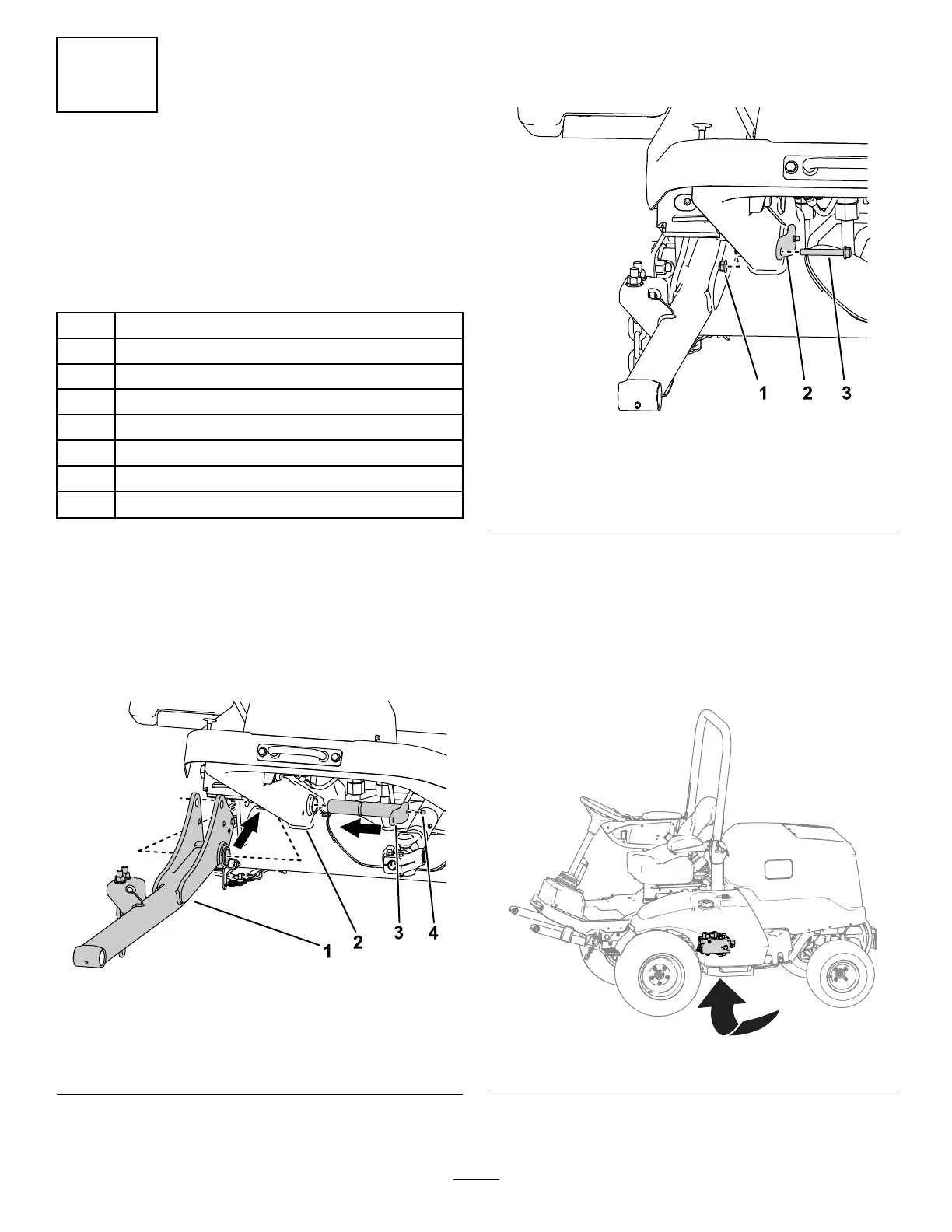
g312023
Figure 6
Right side shown.
1. Lift arm
3. Large pin
2. Machine frame 4. Grease tting
3. Install the grease ttings to the large pins ( Figure
6 ).
4. Use 2 nuts (3/8 inch) and 2 bolts (3/8 x 2-3/4
inches) to secure the large pins to the frame
( Figure 7 ).
g295767
Figure 7
Right side shown.
1. Nut 3. Bolt
2. Large pin
5. Perform the following steps to secure the
hydraulic cylinders to the lift arms:
A. Place a drain pan under the hydraulic
manifold (shown in Figure 8 ).
Note: Y ou must bleed a small amount of
hydraulic uid in order to manually retract
the lift cylinders.
g299920
Figure 8
B. Loosen the hose swivel nut connected to
port C1 of the hydraulic manifold ( Figure 9 ).
14