18
Adjusting the W eight
T ransfer of the Attachment
No Parts Required
Procedure
Perform this procedure only if you are installing
an attachment other than the standard rotary
cutting units (e.g., snowthrower , blade, or ail).
Y ou can change the hydraulic pressure used to
transfer the weight of the attachment to the traction
unit by adjusting the weight-transfer valve of the
hydraulic manifold. For best performance, adjust the
weight-transfer valve so that any bouncing motion of
the attachment is minimal over uneven terrain, but
also adjust the valve so that the attachment does not
ride heavily over at terrain or lower too quickly .
• T o improve the contour-tracking performance of
the attachment as you operate the machine over
uneven terrain, decrease the weight-transfer
(hydraulic) pressure at the hydraulic manifold.
Note: If the attachment casters or the leading
edge of the snowthrower oat above the ground,
the hydraulic pressure of the weight transfer valve
is too high.
• When you are cutting at turf, when the cutting
unit is scalping the grass, if the quality of cut is
uneven from side to side, or the leading edge of a
snowthrower is scraping too heavily , increase the
weight-transfer pressure at the hydraulic manifold.
Note: Increasing weight-transfer pressure also
transfers the weight from the attachment to the
wheels of the traction unit, thereby improving the
traction of the traction unit.
Adjust the weight-transfer pressure as follows:
1. Operate the machine for 10 minutes.
Note: This will warm the hydraulic uid.
2. Park the machine on a level surface, lower the
attachment, engage the parking brake, shut of f
the engine, and remove the key from the switch.
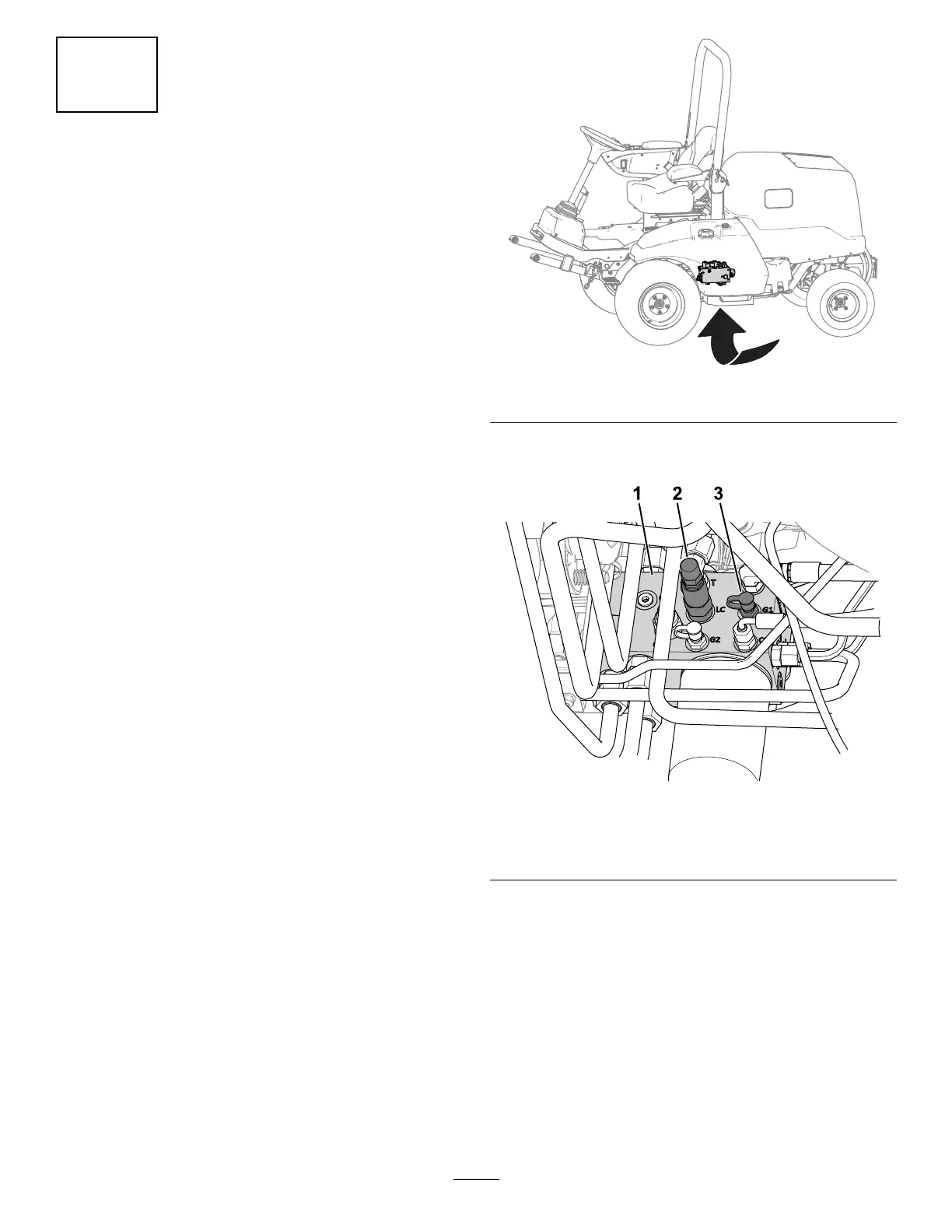
3. Locate the lift manifold from under the machine
( Figure 22 ).
g299920
Figure 22
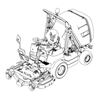
4. Connect a pressure gauge to the test port
(labeled G1 ; refer to Figure 23 ).
g299924
Figure 23
1. Hydraulic manifold 3. T est port (G1)
2. W eight-transfer spool ( LC )
5. At the side of the lift manifold, remove the cap
from the test port (labeled G1 ; refer to Figure
23 ).
6. Loosen the jam nut at the end of the
weight-transfer spool (labeled LC ; refer to Figure
23 ).
7. Start the engine, set the throttle to HIGH IDLE .
8. Use a hex-socket wrench to adjust the
counterbalance valve of the weight-transfer
spool until the gauge indicates the desired
pressure; refer to the following table for
27