1 1
Adjusting the Roll-Bar
Position
Models 31900A, 31901A, and
31907A Only
No Parts Required
Procedure
Raise the roll bar; refer to Raising the Roll Bar ( page
38 ) .
12
Connecting the Battery
Models 31900A, 31901A, and
31907A Only
No Parts Required
Procedure
Connect the battery; refer to Connecting the Battery
( page 59 ) .
13
Installing the Attachment
Parts needed for this procedure:
1
Optional attachment (ordered separately; refer to your
authorized T oro distributor)
2
Socket-head screw (3/8 inch)
2
W asher (3/8 inch)
2
Flange locknut (3/8 inch)
Procedure
Important: When switching attachments,
conrm with your authorized T oro distributor the
correct number of rear weights for that specic
attachment.
Install the front attachment (e.g., cutting unit, ail,
plow blade, or blower); perform the following steps
and refer to your attachment Operator ’ s Manual for
additional installation instructions.
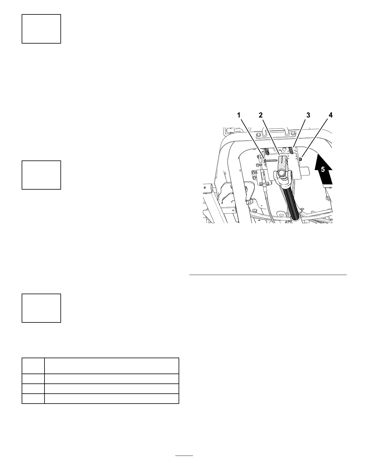
1. While supporting the driveshaft, remove the
capscrew and locknut that secure the driveshaft
yoke to the steering valve-mount bracket ( Figure
16 ), and carefully lower the driveshaft.
Note: Discard the capscrew and locknut.
g340623
Figure 16
1. Capscrew
4. Locknut
2. Driveshaft yoke 5. Front of the machine
3. Steering valve-mount
bracket
2. Ensure that the PT O shaft is aligned; refer to
Aligning the PT O Driveshaft ( page 62 ) .
3. Have an assistant sit in the seat, turn the key
to the O N position, and use the attachment lift
switch to lower the lift arms while you push down
on the lift arms.
4. Align the holes in the lift arm with the holes in the
attachment arm as described in the attachment
Installation Instructions .
5. Align the splines in the driveshaft yoke onto the
splines of the attachment input shaft ( Figure 17 ),
and slide the yoke over the shaft.
19