g340624
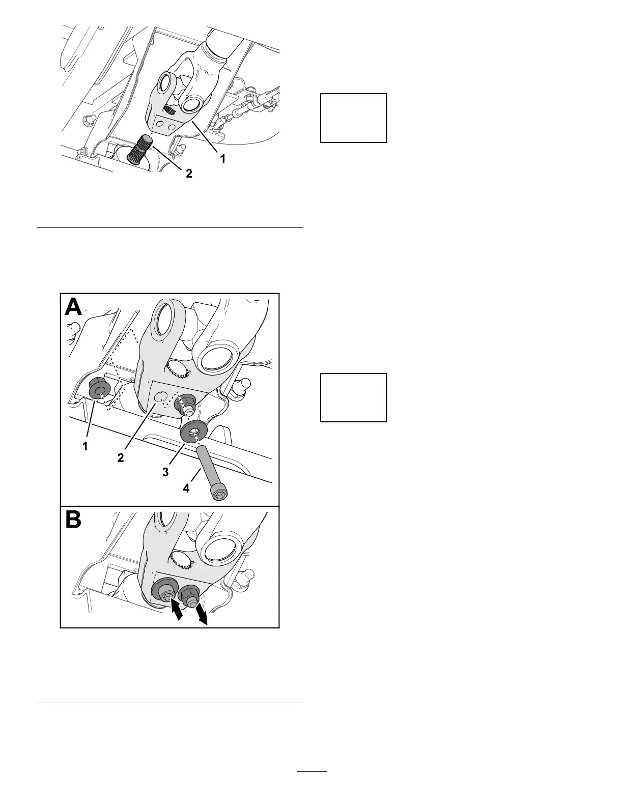
Figure 17
1. Driveshaft yoke 2. Input shaft
6. Assemble a socket-head capscrew (3/8 x 2-1/4
inches) through a washer (3/8 inch) and the hole
in the driveshaft yoke ( Figure 18 ), and secure
the capscrew with a ange-locknut (3/8 inch).
g340626
Figure 18
1. Flange-locknut (3/8 inch) 3. W asher (3/8 inch)
2. Driveshaft yoke 4. Socket-head capscrew
(3/8 x 2-1/4 inches)
7. Assemble a socket-head capscrew (3/8 x 2-1/4
inches) through a washer (3/8 inch) and the hole
in the driveshaft yoke from the opposite direction
( Figure 18 ), and secure the capscrew with a
ange-locknut (3/8 inch).
8. Incrementally torque the locknuts to 61 N∙m (45
ft-lb) in an alternating pattern.
14
Checking the Fluid Levels
No Parts Required
Procedure
Before you start the engine for the rst time, perform
the following uid-level checks:
• Check the engine-oil level; refer to Checking the
Engine-Oil Level ( page 53 ) .
• Check the coolant level; refer to Checking the
Cooling System and Coolant Level ( page 63 ) .
• Check the hydraulic-uid level; refer to Checking
the Hydraulic-Fluid Level ( page 69 ) .
15
Checking the T ire Pressure
No Parts Required
Procedure
Check the tire pressure; refer to Checking the T ire Air
Pressure ( page 35 ) .
Important: Maintain pressure in all tires to
ensure a good quality-of-cut and proper machine
performance. Do not underinate the tires.
20