1. Push down the PT O switch.
2. Start the engine; refer to Starting the Engine
( page 42 ) .
3. Pull up the PT O switch.
Understanding T urnaround
Mode
Engage the turnaround mode whenever you install
the ail mower (Model 02835).
T urnaround mode allows you to quickly raise the ail
mower above the turf when completing a quick turn at
the end of a mowing pass, or while navigating around
obstacles.
When you lower the ail mower to the O PERATING
position, you can quickly press and release the
attachment lift switch rearward to slightly raise the
ail when you perform a quick turn. Once you have
completed the turn, press the lift switch to lower the
ail back to the ground and resume mowing.
Shutting Off the Engine
1. Use the throttle control to lower the engine
speed.
2. Move the PT O switch to the O FF position.
3. Rotate the key switch to the O FF position and
remove the key from the switch.
After Operation
After Operation Safety
General Safety
• Shut of f the engine, remove the key , and wait
for all movement to stop before you leave the
operator ’ s position. Allow the machine to cool
before adjusting, servicing, cleaning, or storing it.
• Clean grass and debris from the cutting units,
muf ers, and engine compartment to help prevent
res. Clean up oil or fuel spills.
• If the cutting units are in the transport position, use
the positive mechanical lock (if available) before
you leave the machine unattended.
• Allow the engine to cool before storing the machine
in any enclosure.
• Remove the key and shut of f the fuel (if equipped)
before storing or hauling the machine.
• Never store the machine or fuel container where
there is an open ame, spark, or pilot light, such
as on a water heater or on other appliances.
• Maintain and clean the seat belt(s) as necessary
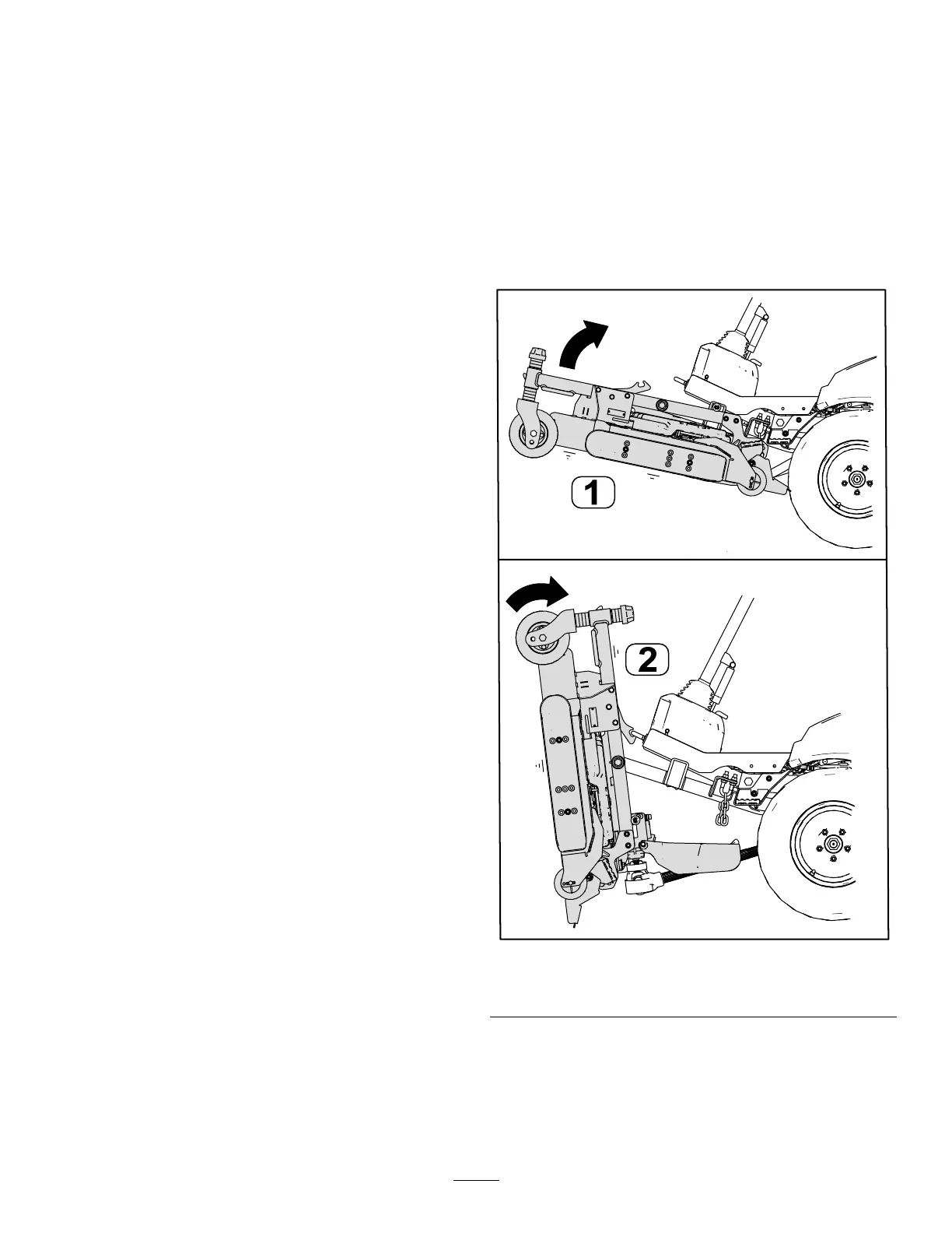
Servicing the Cutting Unit
Y ou can rotate the cutting unit from the T RANSPORT
position ( A in Figure 37 ) to the S ERVICE position ( B in
Figure 37 ). Use the S ERVICE position to maintain the
cutting unit blades or clean underneath the cutting
unit; refer to your cutting unit Operator ’ s Manual .
g258473
Figure 37
1. T RANSPORT position
2. S ERVICE position
Rotating the Cutting Unit to the
S ERVICE Position
Perform this procedure to rotate the cutting unit from
the T RANSPORT position to the S ERVICE position.
43