4 Replacement Procedures 4.13 Cover assembly and Base assembly
4 Replacement Procedu es
4.13 Cover assembly and Base assembly
r
Removing the Cover assembly and Base assembly
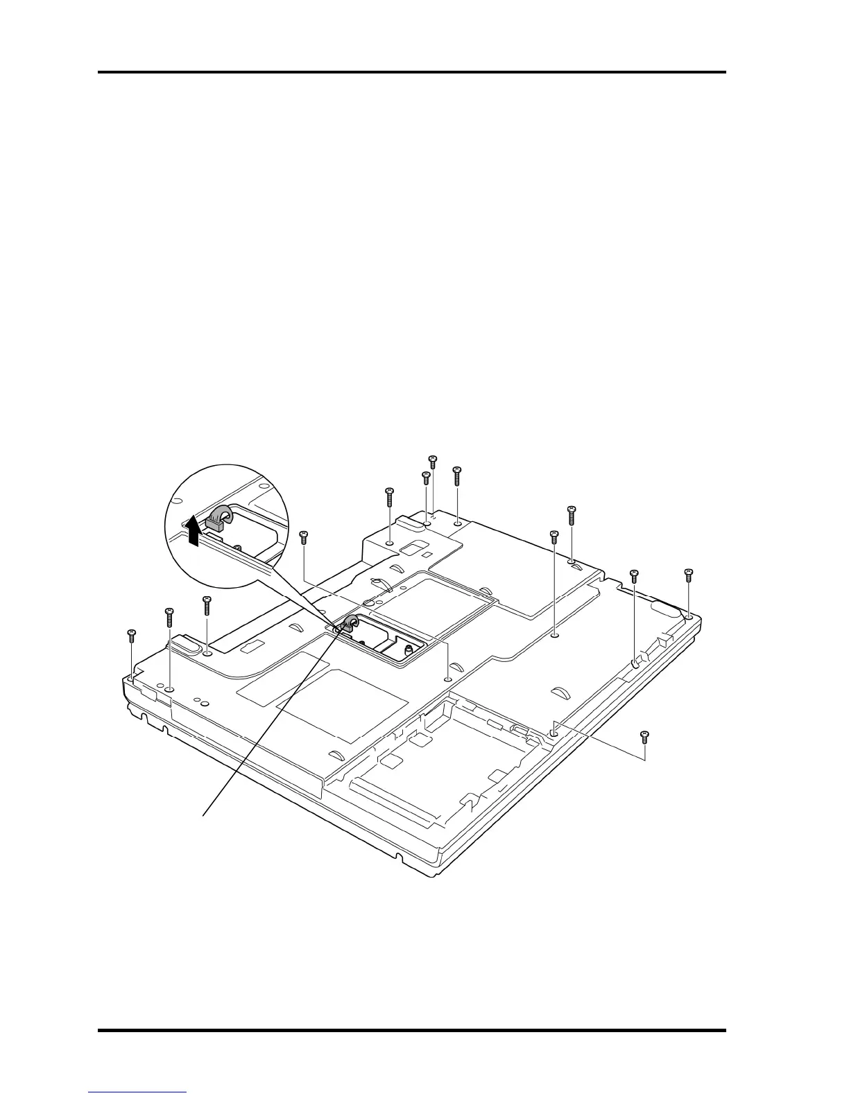
To remove the cover assembly and base assembly, follow the steps below and refer to Figure
4-21 and 4-22.
1. Close the display and turn over the computer.
2. Remove the following screws.
• M2.5×6B FLAT HEAD screw ×8 (“6” in the figure below)
• M2.5×16B FLAT HEAD screw ×5 (“16” in the figure below)
3. Disconnect the USB cable from the connector CN4612 on the system board.
“6”
“6”
“6”
“6”
“6”
“6”
“16”
“16”
“6”
“16”
“6”
“16”
“16”
USB cable
(Connected to CN4612)
Figure 4-21 Removing the cover assembly and base assembly (1)
4-36 [CONFIDENTIAL] TECRA A9/TECRA S5/TECRA P5/Satellite Pro S200 Maintenance Manual (960-633)

 Loading...