4 Replacement Procedures 4.22 North bridge (and GPU) heat sink/CPU heat sink/Fan/CPU
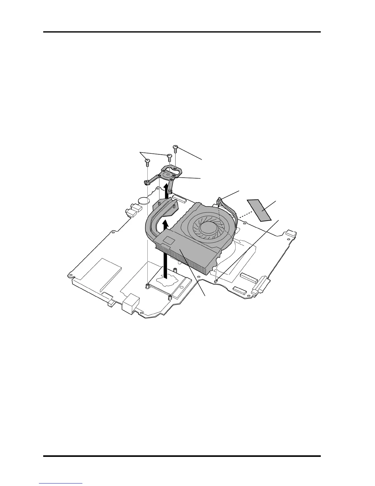
5. Remove the following screws in the reverse order of the numbers marked on the CPU
hold plate.
• M2×4B BIND screw ×3
6. Remove the CPU hold plate.
7. Peel off the acetate tape and disconnect the fan cable from the connector CN8771
on the system board.
8. Remove the CPU heat sink (with a fan).
M2×4B BIND
M2×4B BIND
CPU hold plate
Fan cable
CN8771
CPU heat sink
(With a fan)
cetate tape
Figure 4-38 Removing the CPU heat sink (with a fan)
4-64 [CONFIDENTIAL] TECRA A9/TECRA S5/TECRA P5/Satellite Pro S200 Maintenance Manual (960-633)

 Loading...