E6582233
F-2
6
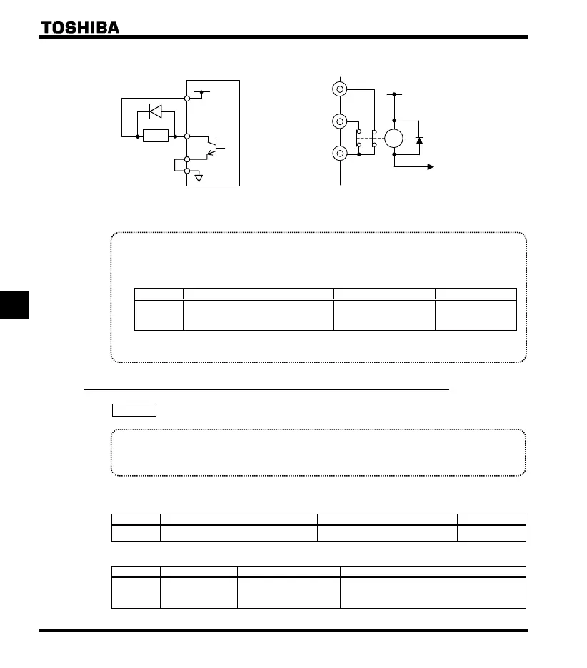
FLA
FLC
FLB
RY
+24V
An example of the connection of the open collector
OUT terminal
sink lo
ic
An example of the connection of the relay
output terminals
Output terminal setting
Default outputs low-speed signal (ON signal) to OUT terminal. This setting must be changed to invert
the polarit
of the si
nal.
[Parameter setting]
Title Function Ad
ustment ran
e Default settin
Output terminal selection 1A (OUT)
0-255
(Refer to section 10.6)
4: LOW (Low-
speed detection
si
nal
Setting value 5 is reverse signal.
Set to output to FLA-FLC-FLB terminals.
6.1.2 Output of designated frequency reach signal
: Speed reach detection band
Function
When the output frequency becomes equal to the setting by designated frequency , an ON
or OFF signal is generated.
[Parameter setting]
Parameter setting of designated frequency and detection band
Title Function Ad
ustment ran
e Default settin
Speed reach detection band 0.0 - (Hz) 2.5
Parameter setting of output terminal selection
Title Function Ad
ustment ran
e Settin
Output terminal
selection 1A
OUT
0-255
(Refer to section 10.6)
6: RCH (Output frequency attainment signal
(acceleration/deceleration completed))
Setting value 7 is reverse signal.
Note: Set to output to FLA-FLC-FLB terminals.
+24V
OUT
NO
CC
Ry
P24

 Loading...


