E6582233
B-4
2
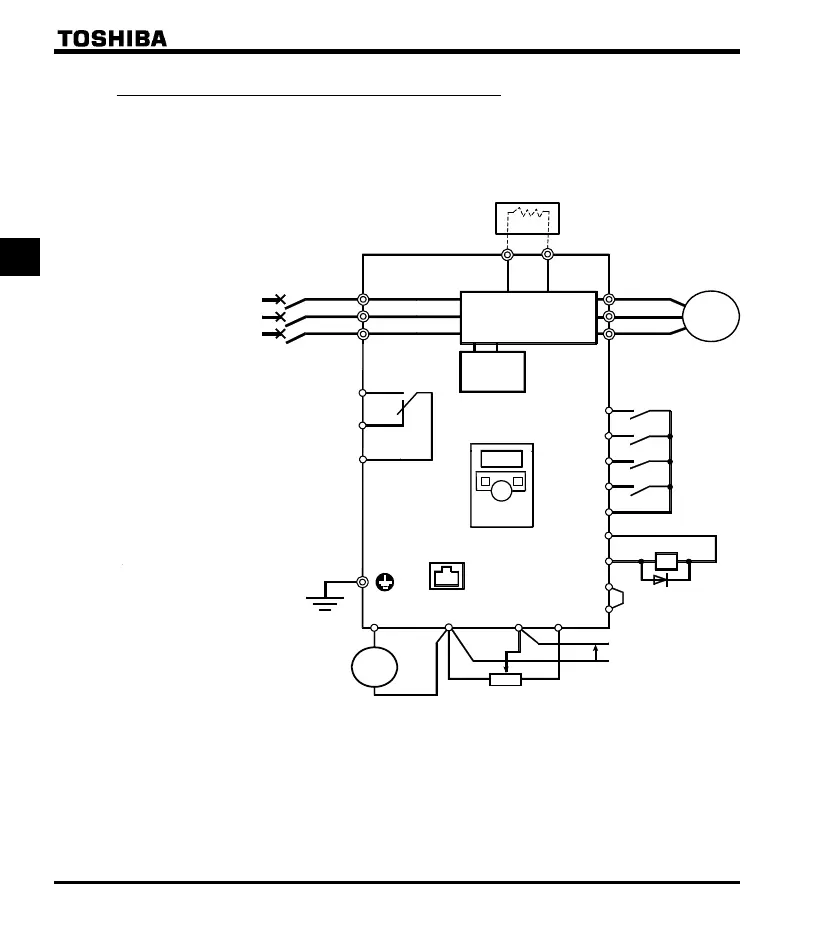
2.2.1 Standard connection diagram 1
This diagram shows a standard wiring of the main circuit.
MCCB
R/L1
S/L2
T/L3
U/T1
V/T2
W/T3
Motor
F
R
S1
S2
CC
P24
OUT
NO
CC
FM
CC VI
P5
+
+
-
-
PA/+ PB
Meter
Voltage signal: 0-5V/0-10V
(Current signal: 4-20mA)
External potentiometer (1k-10k)
Protective function
activation output
Ry
VF-nC3C
Power
circuit
Forward run command
Reverse run command
Preset-speed command 1
Preset-speed command 2
Common
Standard connection diagram - SINK (Negative) (common:CC)
7.5V-1mA
(or 0-10V/4-20mA)
Low-speed
signal output
*2
*1: VFNC3C-4004P, 4007P models don’t
have the PA/+ and the PB terminals
and cannot be used with Braking
resistor.
*2: When using the OUT output terminal in
sink logic mode, short the NO and CC
terminals.
Control
circuit
I M
Frequency
me t er
( a mme t e r )
Operation panel
FLC
FLB
FLA
*3: When external potentiometer is connected
by using P5 terminal, set the parameter
f109=3.
RS485
communication
connector
*4
*4: When VI terminal is used as a logic
input terminal, refer to page B-12.
Main circuit power supply
3ph-400V class: three-phase 380-460V
-50/60Hz
*3
Braking resistor(Option)
*1
VF-nC3E
VFNC3E-4004P, 4007P
*5
*5: Calibration is needed before using the meter.

 Loading...


