E6582233
B-6
2
2.3 Description of terminals
2.3.1 Power circuit terminals
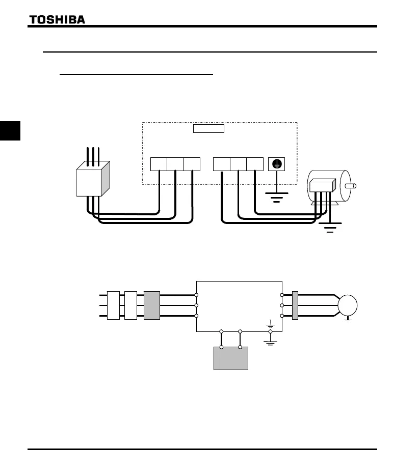
This diagram shows an example of wiring of the main circuit. Use options if necessary.
Power supply and motor connections
Connections with peripheral equipment
Motor
Power
supply
Inverter
Braking resistor
Molded-case
circuit braker
R/L1
S/L2
T/L3
PA/+
PB
V/T2
U/T1
W/T3
IM
Magnetic
contactor
Input AC
reactor
Zero-phase
reactor
Note 1: The PA/+ and PB terminals are not provided for VFNC3E-4004P, 4007P models.
Power supply
S/L2 T/L3
Motor
No-fuse
breaker
Connect the power
cables to R/L1, S/L2,
and T/L3.
Connect the motor
cables to U/T1, V/T2
and W/T3.
E
U/T1
V/T2 W/T3
R/L1
VF-nC3E

 Loading...


