E6582233
G-9
7 7
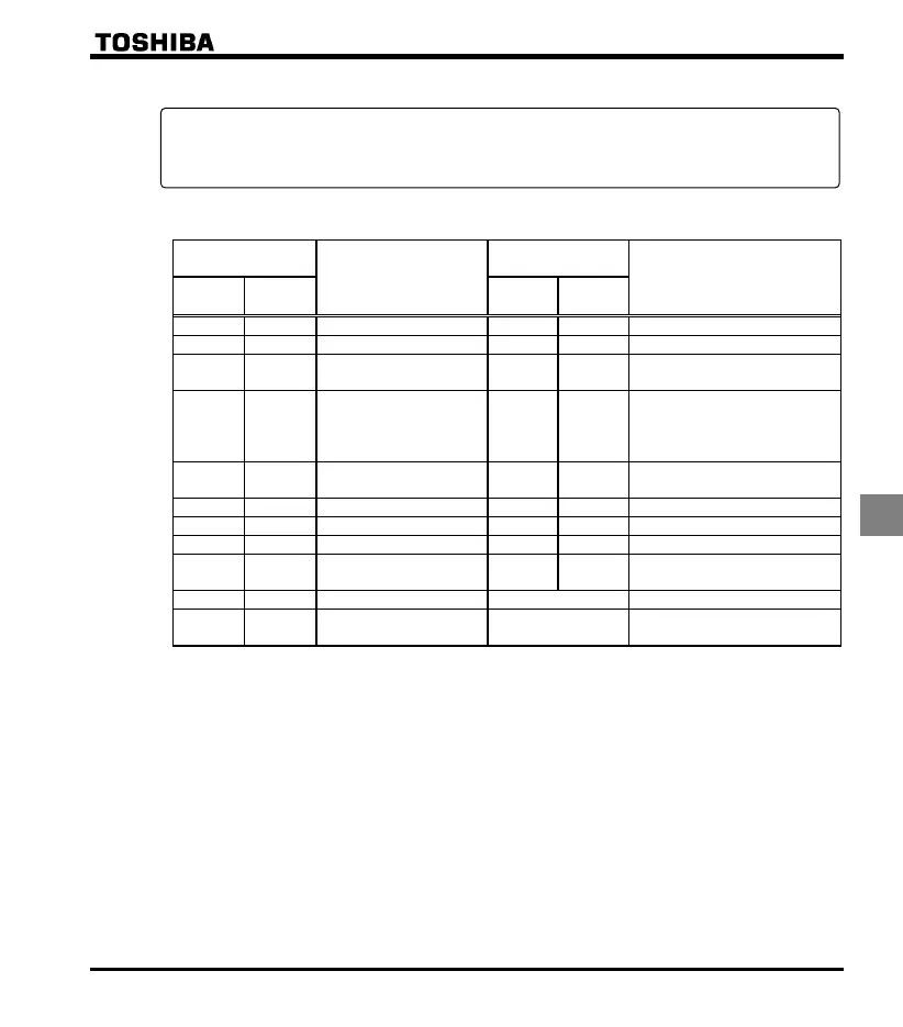
List of output terminal function settings
List of detection levels for output terminal selection
Parameter programmed
value
Function
Parameter
programmed value
Function
Positive
logic
Negative
logic
Positive
logic
Negative
logic
Frequency lower limit Small current detection
Frequency upper limit Over-torque detection
Low-speed detection
signal
Run/Stop
Output frequency
attainment signal
(acceleration/deceleration
completed)
Cumulative operation time alarm
Set frequency attainment
signal
Forward/reverse run
Fault signal (trip output) RS485 communication error
Over-current pre-alarm Designated data output
Overload pre-alarm Parts replacement alarm
Overheat pre-alarm Fault signal
(output also at a ready)
Overvoltage pre-alarm Always OFF
Power circuit
undervoltage detection
Always ON
Note 1) ON with positive logic : Open collector output transistor or relay turned ON.
OFF with positive logic : Open collector output transistor or relay turned OFF.
ON with negative logic : Open collector output transistor or relay turned OFF.
OFF with negative logic : Open collector output transistor or relay turned ON.
☆ Refer to section 10.6 for details about the output terminal functions or levels.
<Explanation of terminology>
Alarm …... Alarm output when a setting has been exceeded.
Pre-alarm …... Alarm output when the inverter may cause a trip during continued operation.

 Loading...


