E6582233
H-2
8
8.2 Status monitor mode
8.2.1 Status monitor under normal conditions
In this mode, you can monitor the operation status of the inverter.
To display the operation status during normal operation:
Press the MODE key twice.
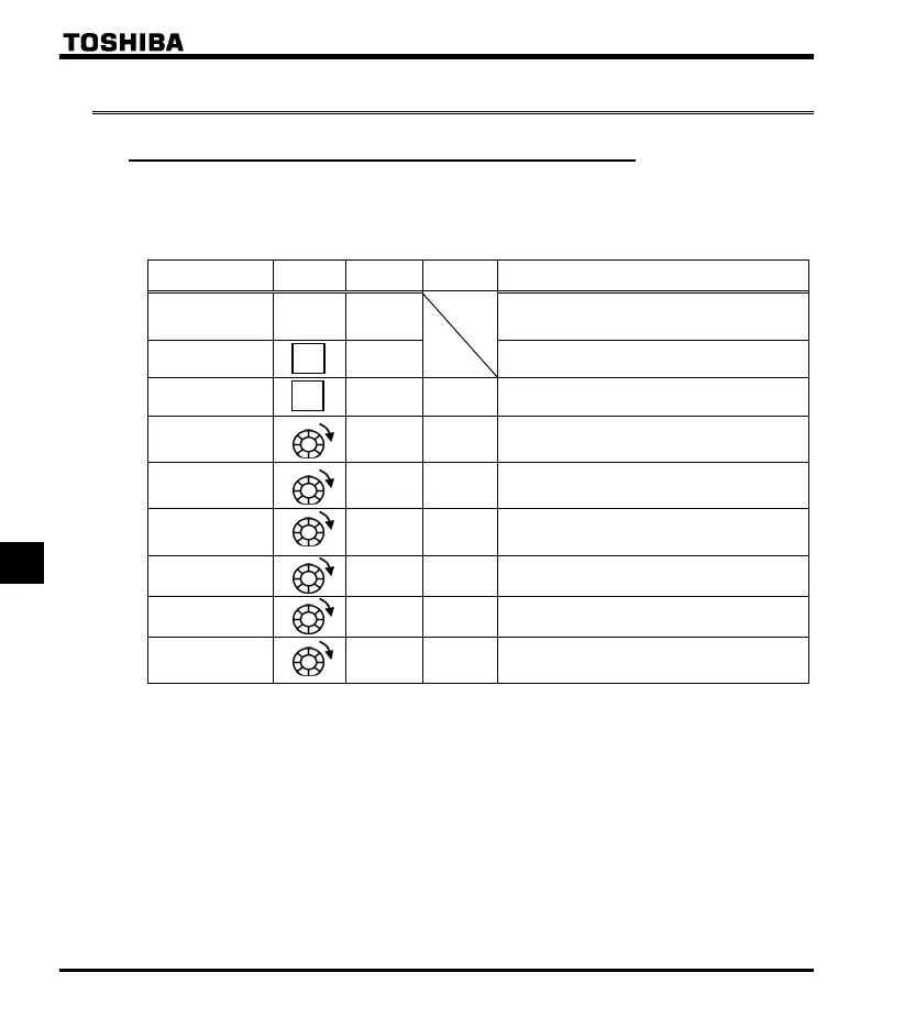
Setting procedure (eg. operation at 40Hz)
Item displayed
Panel
operated
LED
displa
Communic
ation No.
Description
Operation
frequency *
The operation frequency is displayed (Operation at
60Hz). (When standard monitor display selection
is set at 0 [operation frequenc
]
Parameter setting
mode
The first basic parameter “” (history function)
is displayed.
Direction of
rotation
FE01
The direction of rotation is displayed.
(: forward run, : reverse run)
Operation
frequency
command *
FE02
The operation frequency command value (Hz/free
unit) is displayed.
In case of =
Output current *
FE03
The inverter output current (load current) (%/A) is
displayed.
In case of =
Input voltage *
FE04
The inverter input voltage (DC detection) (%/V) is
displayed.
In case of =
Output voltage *
FE05
The inverter output voltage (%/V) is displayed.
( In case of = )
Inverter
load factor *
FE27
The inverter load factor (%) is displayed.
( In case of = )
Operation
frequency *
FD00
The operation frequency (Hz/free unit) is
displayed.
In case of =
(Continued overleaf)
* Monitor items can be selected by setting parameters to , (). Note 11
Refer to page H-8 for notes.
Note 1
Note 2
Note 3
MODE
MODE

 Loading...


